
Yokogawa ROTOMETER RAMC Metal Variable Area Flow Meter
Damping setting (F21): Smooth output signal for 0/1/5/10 seconds to reduce the impact of flow fluctuations, with a default of 1 second
Current output (F3-) 4-20mA/0-20mA switch 2-wire system default 4-20mA, adjustable zero point (F32) and range (F33), 20 μ A per step
Fault detection (F4-) error code displayed as "08" indicates that the float is stuck and needs to be cleaned or automatically zeroed (F74)
Float stuck detection (F7-) on/off, monitoring lower limit (5%/15%/30% Qmax), monitoring time 5/15 minutes optional. If there is no signal fluctuation beyond the deadline, a fault alarm will be triggered
(2) HART 7 communication (- J type exclusive)
Communication features: Supports 2-wire 4-20mA overlay with HART signal, enables remote parameter configuration and data reading (such as real-time flow, cumulative value, diagnostic information), supports multi slave mode (up to 63 devices), and can set polling address 1-63.
Core functions:
Process variable monitoring: real-time reading of flow rate, temperature, current output, etc;
Fault diagnosis: detect RAM errors, ADC faults, EEPROM anomalies, etc;
Burst mode: Continuously sending specified data (such as traffic+cumulative value) to reduce communication latency;
Trend configuration: Record 12 sets of historical data, with adjustable sampling intervals of 1-2 hours.
2. Limit switch (/K1-/K10 options)
Type and Function:
Standard type (/K1-/K3): Supports MAX/MIN dual contacts and complies with EN 60947-5-6 (NAMUR) standard;
Fault safe type (/K6-/K10): When power is cut off, the contacts automatically switch to a safe state and require a dedicated power supply (such as/K2E,/W4F).
Parameter configuration: Set the MIN-MAX/MIN-MIN/MAX-MAX function by switching the direction of the power supply. For example, when the K3 option is paired with the W2B power supply, the S1/S2 relay position determines the contact logic.
Explosion proof certification and safety regulations
1. Explosion proof type and applicable scenarios
RAMC provides two types of explosion-proof designs: intrinsic safety (Ex ia) and explosion-proof (Ex db), covering major certification systems worldwide. The core parameters are as follows:
Certification Type Model Options Explosion proof Mark Applicable Area Key Parameters (Electronic Transmitter)
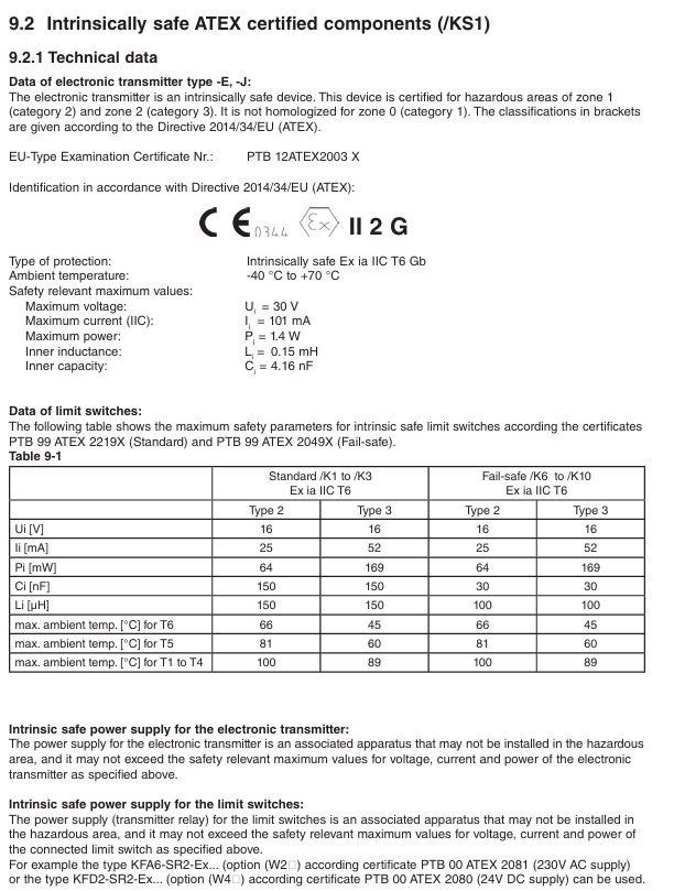
ATEX/KS1 (intrinsic safety) Ex ia IIC T6 Gb Zone 1/2 (gas), Zone 21/22 (dust) Ui=30V, Ii=101mA, Pi=1.4W
IECEx/ES1 (Intrinsic Safety) Ex ia IIC T6 Gb Global Explosion proof Zone Li=0.15mH, Ci=4.16nF
NEPSI (China)/NS1 (Intrinsic Safety) Ex ia IIC T6 Gb Explosion proof Area Environmental Temperature in China -40 ° C~+70 ° C
FM/UL (US Canada)/FS1 (Intrinsic Safety) Class I Div1 GP A-D T6 US Canada Zone 1/Zone 2 Vi=30V, Ii=100mA, Pi=1.4W
EAC (Eurasian Economic Union)/GS1 (Explosion proof+Dust) Ex db IIC T6 Gb/Ex tb IIIC T80 ° C Db Eurasian Union Explosion proof Area Surface Temperature ≤ 80 ° C (T6)
2. Explosion proof installation and operation taboos
Intrinsic safety requirements:
The power supply must be a certified associated device (such as KFA6-SR2-Ex2. W) installed in a safe area;
The cable capacitance/inductance should be ≤ Ci/Li (e.g. Ci=4.16nF, Li=0.15mH) to avoid safety risks caused by exceeding the limit.
Explosion proof type requirements:
Power off and wait for 15 minutes before opening the lid to ensure the safety of the internal gas;
The cable sealing sleeve must comply with the IEC 60079-1 standard and be sealed with certified blind plugs for entry purposes;
When the shell is damaged (such as the observation window breaking), it should be immediately stopped to avoid the failure of explosion-proof performance.
Maintenance and troubleshooting
1. Daily maintenance and regular inspections
Routine inspection (weekly):
Pointer/display screen: Confirm that the flow indication matches the actual working conditions without any jamming or jumping;
Sealing state: The flange and cable sealing sleeve have no leakage, and the shell has no corrosion;
Explosion proof mark: The label is clear, without wear or detachment.
Regular maintenance (every 6 months):
Cleaning: The measuring tube and float need to be disassembled and cleaned (avoiding the use of corrosive solvents), and the magnetic properties of the float should be checked for normal operation;
Calibration: The electronic transmitter needs to be verified for 4-20mA output accuracy through a HART communicator, and the limit switch needs to be tested for contact action reliability;
Grounding inspection: The grounding resistance is ≤ 100 Ω, and the grounding terminal is not loose.
2. Common faults and troubleshooting
Possible causes and solutions for the fault phenomenon
The pointer is unresponsive/stuck, the float is stuck by impurities, and the inner wall of the measuring tube is scaled. Disassemble and clean the float and measuring tube, and replace the float if necessary
Electronic transmitter has no output power supply fault, calibration EEPROM is missing, wiring is loose. Check power supply (24VDC ± 10%), reinsert EEPROM, and tighten wiring terminals
HART communication failure, load resistance not between 250-600 Ω, pole address conflict, adjust load resistance, reset unique pole address (1-63)
- OMRON
- ABB
- General Electric
- EMERSON
- Honeywell
- HIMA
- ALSTOM
- Rolls-Royce
- MOTOROLA
- Rockwell
- Siemens
- Woodward
- YOKOGAWA
- FOXBORO
- KOLLMORGEN
- MOOG
- KB
- YAMAHA
- BENDER
- TEKTRONIX
- Westinghouse
- AMAT
- AB
- XYCOM
- Yaskawa
- B&R
- Schneider
- KONGSBERG
- NI
- WATLOW
- ProSoft
- SEW
- ADVANCED
- Reliance
- TRICONEX
- METSO
- MAN
- Advantest
- STUDER
- DANAHER MOTION
- Bently
- Galil
- EATON
- MOLEX
- DEIF
- B&W
- ZYGO
- Aerotech
- DANFOSS
- Beijer
- Moxa
- Rexroth
- Johnson
- WAGO
- TOSHIBA
- BMCM
- SMC
- HITACHI
- HIRSCHMANN
- Application field
- XP POWER
- CTI
- TRICON
- STOBER
- Thinklogical
- Horner Automation
- Meggitt
- Fanuc
- Baldor
- SHINKAWA
- Other Brands
- UniOP
- KUKA
- Iba
- Beckhoff
-
 Basler BE3-51-3E1E1 9320000110 24VDC Overcurrent Relay
 -
 Basler UFOV 260A Underfrequency Overvoltage Module
 -
 Basler 50F4EA1PA0N0F Instantaneous Overcurrent Relay
 -
 Basler BE1-50 Instantaneous Overcurrent Relay
 -
 Basler BE1-32 Solid State Protective Relay
 -
 Basler SCP 250-G-60 VAR Power Factor Controller
 -
Basler BE1-59N A5EE1KC0N0F Ground Fault Relay
-
Basler BE1-79A Reclosing Relay
-
 Basler BE1-32R E1EA1OA0N0F Reverse Power Relay
 -
 Basler DCQA-103 DCQC104-1 CMX-7D Circuit Board
 -
 Basler SSR125-12 Static Regulator 918500102
 -
 Basler 90 17709 112 Regulator Control Board
 -
 Basler AVC63-4 AVC634 Voltage Regulator
 -
 Basler 9 1049 04 100 PC Board Control Module
 -
 Basler SR4A-2B03B3A Static Voltage Regulator
 -
 Basler SR8A-2B15B3A Static Voltage Regulator
 -
 Basler KR7FFX Static Regulator 840V
 -
 Basler EL200-7 Voltage Regulator 90-660VAC 7A
 -
 Basler PRP210-1 Reverse Power Relay 9056300102
 -
 Basler SSR 63-12 Static Regulator 600VAC
 -
 Basler 9289901106 Digital Board
 -
Basler DECS100 Voltage Regulator DECS100A01
-
 Basler Electric CEM-2020 Contact Expansion Module
 -
 Basler Electric BE3-25-1 C1 N4 Synchronizing Check Relay
 -
 Basler Electric ACA2000-50GM GigE Camera 2MP 50fps
 -
 Basler Electric ACA2240-20GMSYM GigE Camera Sony IMX264
 -
 Basler BE1-50G Ground Overcurrent Relay
 -
 Basler PRS250 Veri-Sync Relay
 -
Basler MOC2199 Output Module
-
 Basler UFOV 260A Underfrequency Overvoltage Module
 -
 Basler BE-15482-001 Control Module
 -
Basler LSP4-7 Protective Relay
-
 Basler SCP 250-G-60 VAR Power Factor Controller
 -
Basler BE146N Negative Sequence Overcurrent Relay
-
Basler APR63-5 Automatic Voltage Regulator
-
Basler 9507900107 SR8A Retrofit Voltage Regulator
-
Basler BE1-320 Directional Power Relay
-
 Basler KR7F Voltage Regulator 9116200100
 -
Basler UFOV 260A Overvoltage Protective Module
-
 Basler AEC63-7 Analog Excitation Controller
 -
Basler 9992D90G01 Control Module
-
 Basler 6966D22G01 Control Board
 -
Basler 6965D40G01 Control Board
-
 Basler BE1-50/51M-104 Overcurrent Relay
 -
 Basler BE1-BPR Programmable Breaker Relay
 -
 BASLER Electric SSR 125-9 1256 00 102 Static Voltage Regulator
 -
 Basler Electric MVC 112 Manual Voltage Control
 -
 Basler Electric 9321000102 Control Module
 -
 Basler Electric RA-70-MDCT7 Rectifier Assembly
 -
 Basler Electric ACA1300-60GM GigE Camera
 -
 Basler Electric 6427C85G01 Interface Board
 -
Basler Electric 6965D05G01 Control Board
-
Basler Electric ACA2500-14UC Current Transducer
-
 Basler Electric 9170206111 Protective Relay
 -
 Basler Electric BE1-11-G6D1M1J1P0E000 Protection Relay
 -
Basler Electric BE1-50/51B-107 Overcurrent Relay
-
 Basler 9121000106 Voltage Controller
 -
 Basler B3E-E1P-A0N0F Solid State Protective Relay
 -
 Basler 9121000106 Manual Voltage Control
 -
Basler PRP320 Motor Pull-out Relay
-
 Basler SSE-N 250-9KW Shunt Exciter Regulator
 -
 Basler BE1-50-51B-107 Overcurrent Relay
 -
 BASLER ELECTRIC MVC 108 MANUAL VOLTAGE CONTROL MODULE 9 0370 00 102
 -
Basler BE1-59N-A7E-D1J-D0N0F Ground Overvoltage Relay
-
Basler BE1-46N-G1E-B8P-B0N0F Negative Sequence Overcurrent Relay
-
Basler BE1-951 Overcurrent Protection System
-
 Basler Electric MOC2199 Motor Operated Potentiometer
 -
 Basler Electric BE1-60 Voltage Balance Solid State Relay B1FA1C1M1F
 -
Basler Electric BE1-67N Directional Overcurrent Relay
-
Basler Electric PIA2400-17GM Interface Module
-
 Basler Electric V6RAB Rectifier Module
 -
Basler Electric BE1-32R Reverse Power Relay B2E E1R A0N1F
-
Basler Electric IFM-150 Firing Circuit Chassis 120V AC
-
 Basler Electric IFM-102 Firing Circuit Chassis 120V AC
 -
 Basler Electric 9170206111 NSNP Control Module
 -
Basler Electric SSR 63-12 Static Voltage Regulator
-
 Basler UFOV 260A Overvoltage Protective Module
 -
Basler SCA1300-32GM CCD Camera Lens Enclosure
-
 Basler BA1-27 Under Voltage Relay
 -
Basler 149D866G06 Control Board
-
 Basler 9072300130 Power Supply Module
 -
Basler CBS 305 Current Boost System
-
 Basler BE1-60 Voltage Balance Relay
 -
 Basler Electric CBS 212 Current Boost System Sensing 120/240VAC 50/60Hz 10VA
 -
 Basler MVC-300 Manual Voltage Control Unit
 -
Basler SSR125-12 Static Voltage Regulator 918500102
-
Basler SR32A2B05B3E Static Voltage Regulator
-
Basler Electric BE1-59N Ground Fault Overvoltage Relay
-
 Basler Electric 9110000113 Excitation Module
 -
Basler Electric 90-72300-114 Control Accessory
-
Basler Electric PRS-250 Protection Relay System
-
Basler Electric BE1-50/51M-109 Overcurrent Relay
-
 Basler Electric SR4A1B10B3E Static Voltage Regulator
 -
 Basler Electric CBS 212 Current Boost System
 -
Basler Electric SR32A2B05B3E Static Voltage Regulator
-
Basler Electric MOC2207 Motor Operated Potentiometer
-
 Basler Electric SR4A1B05A3E Static Voltage Regulator
 -
Basler Electric BE1-32R Power Relay B2EE1PA0N1F
-
Basler BEI-81 Underfrequency Relay
-
Basler CBS 212A Current Boost System
-
Basler SSR 63-12 Static Voltage Regulator
-
 Basler DGC-2020 Digital Genset Controller
 -
Basler BE1-32 Reverse Power Relay
-
 Basler BE1-50/51B-207 Overcurrent Relay
 -
Basler BE1-951 Overcurrent Protection System
-
 Basler 9073800-103 Power Supply
 -
Basler SCA1300-32FC CCD Camera
-
Basler 9073800-103 Power Supply
-
Basler SCA1300-32FC CCD Camera
-
 Basler L304KC Protective Relay
 -
 Basler BE3-25-1S1N4 Time Overcurrent Relay
 -
Basler 9032300113 Excitation Support System
-
Basler BE1-59N Ground Overvoltage Relay
-
Basler MVC-300 Manual Voltage Control Unit
-
Basler MOC2102 Potentiometer
-
 Basler BE1-87G Generator Differential Relay
 -
 Basler Electric DECS-200 Digital Excitation Control System
 -
Basler Electric DECS 125-15-B2C5 Digital Excitation System
-
 Basler Electric PLA2400-12GM Power Supply
 -
 Basler Electric BE1-50/51B-235 Overcurrent Relay
 -
Basler Electric BE1-27/59 Undervoltage Overvoltage Relay
-
Basler Electric CEM-2020 Contact Expansion Module
-
Basler Electric BE1-32R Solid State Power Relay
-
 Basler Electric BE1-700 Digital Generator Management Relay
 -
Basler Electric BE1-59N Ground Fault Overvoltage Relay
-
Basler Electric BE10493002 Protection Module
-
 Basler Electric BEI-79A1AA5CA3M1F Digital Annunciator
 -
Basler Electric SSR 32-12 Static Voltage Regulator


