
YASKAWA ∑ - V series AC servo drive
YASKAWA ∑ - V series AC servo drive
Core positioning
The YASKAWA ∑ - V series AC servo drive focuses on the entire lifecycle of design, testing, adjustment, and maintenance. It is compatible with SGDV series servo amplifiers and SGMMV/SGMJV/SGMAV rotary servo motors, as well as SGMCV/SGMCS direct drive servo motors. Its core applications include high-frequency, high-speed, and high-precision positioning scenarios (such as automated production lines, precision machine tools, robots, etc.), and it also specifies compliance requirements and safety operating standards such as UL in North America, CE in the European Union, and UKCA.
Product Core Parameter System
(1) Power supply and electrical parameters
Power supply type, model series, voltage range, frequency, continuous output current, instantaneous maximum output current
Single phase 100V SGDV-F series (R70F/R90F/2R1F/2R8F) 100-115VAC,+10%/-15% 50/60Hz 0.66-2.8 Arm 2.1-9.3 Weapon
Single phase 200V SGDV-A series (120A21A008000) 220-230VAC,+10%/-15% 50/60Hz 11.6 weapons 28 weapons
Three phase 200V SGDV-A series (R70A/1R6A/3R8A, etc.) 200-230VA,+10%/-15% 50/60Hz 0.66-78.0 weapons 2.1-170 weapons
Three phase 400V SGDV-D series (1R9D/3R5D/8R4D, etc.) 380-480VAC,+10%/-15% 50/60Hz 1.9-37.2 weapons 5.5-85 weapons
(2) Performance indicators
Speed control range: 1:5000 (the lower limit should be lower than the rated torque without causing the motor to stop)
Speed regulation accuracy: ± 0.01% (rated speed) when the load changes from 0% to 100%; 0% when voltage fluctuation is within ± 10%; ± 0.1% when the temperature changes by 25 ± 25 ℃
Repeatability of torque control: ± 1%
Positioning completion accuracy: can be fine tuned through electronic gear ratio (Pn20E/Pn210) and positioning completion width (Pn522), with a minimum reference unit of 1 μ m
Response characteristics: Soft start time 0-10s (acceleration/deceleration can be independently set)
(3) Environmental and Protection Parameters
Working temperature: 0-55 ℃; Storage temperature: -20-85 ℃
Relative humidity: ≤ 90% RH (no condensation, no freezing)
Vibration resistance: 4.9m/s ²; Impact resistance: 19.6m/s ²
Protection level: IP10 (to avoid contact with corrosive gases, dust, and oil-water)
Altitude limit: ≤ 1000m
Pollution level: Level 2
Key operations and configuration system
(1) Panel and digital operator
1. Core components
Seven segment LED display: displays servo status, alarm codes, parameter values
Function keys (MODE/SET, DATA, JOG/SVON, etc.): used for parameter configuration, utility function execution, and manual operation
Indicator lights: CHARGE (main circuit capacitor charging), L1/L2 (communication data transmission), CN (communication connection normal)
2. Core operating procedures
Parameter configuration: Switch to the "PRM/MON" menu using the MODE/SET keys, select the parameter (Pn series) using the directional keys, modify the value using the DATA key and save it
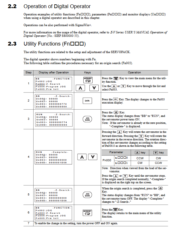
Utility function execution: Switch to the "Function" menu with MODE/SET keys, select Fn code (such as Fn201 advanced self-tuning), and press the DATA key to start
Monitoring view: Switch the MODE/SET key to the "PRM/MON" menu, switch to the monitoring item starting with "Un", and check the motor speed (Un000), torque (Un002), etc
(2) Parameter classification and core parameters
1. Parameter classification
Setup parameter: Basic operating condition configuration (such as Pn002 encoder type, Pn00B single-phase/three-phase power supply selection), after modification, it needs to be restarted to take effect
Tuning parameters: Control gain, filter, etc. (such as Pn100 speed loop gain, Pn102 position loop gain), partially effective in real-time
2. High frequency core parameters
Parameter Code Parameter Name Function Description Typical Setting Range
Pn002 encoder type selection switches between absolute/incremental encoder mode n. 0 (absolute), n. 1 (incremental)
Pn00B. 2 Power Supply Type Selection Three phase 200V Model Switching Single phase/Three phase Input 0 (Three phase), 1 (Single phase)
PN103 moment of inertia ratio matching motor and load inertia, affecting stability 1-1000 (adjusted according to actual load)
Pn20E/PN210 electronic gear ratio adjustment reference unit to actual displacement ratio 1-1073741824
Pn402/PN403 forward/reverse torque limit protection for mechanical loads, preventing overload from 0-800 (unit: rated torque%)
When the width positioning error of Pn522 positioning is less than this value, output the completion signal 0-1073741824 (reference unit)
(3) MECHATROLINK-III Communication Configuration
1. Hardware settings
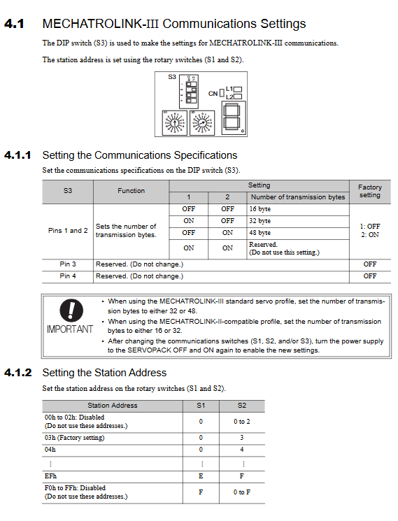
Station address: Set by rotating switch S1 (high), S2 (low), range 03h EFh (disable 00h-02h, F0h FFh)
Number of transmitted bytes: set through DIP switch S3, 16/32/48 bytes (standard servo profile requires 32/48 bytes)
Wiring: CN6A/CN6B connector, shielded twisted pair, maximum distance between stations 75m, terminal needs to be connected to 220-470 Ω matching resistor
2. Communication parameters
Protocol: MECHATROLINK-III
Baud rate: 100Mbps
Transmission cycle: 125 μ s, 250 μ s, 500 μ s, 750 μ s, 1.0-4.0ms (0.5ms step)
Core commands: CONNECT (establish communication), SENS-ON (read absolute encoder data), SV_SON (servo enable)
Wiring and installation specifications
(1) Wiring system
1. Main circuit wiring (power circuit)
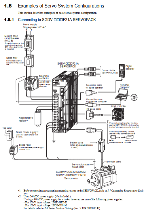
Terminal definitions: L1/L2/L3 (power input), U/V/W (motor wiring), B1/B2/B3 (regenerative resistance), FG (grounding)
Cable requirements: HIV series heat-resistant polyvinyl chloride insulated wire, with a cross-sectional area ranging from 1.25mm ² (low power) to 22mm ² (high power) depending on the model
Wiring principle:
Three phase power supply needs to distinguish phase sequence, single-phase power supply is connected to L1/L2 (L3 suspended)
Regenerative resistor: Some models require the removal of the B2-B3 short-circuit and external connection, while models such as 470A/550A require an external regenerative resistor unit
Grounding: Independent grounding, 200V series grounding resistance ≤ 100 Ω, 400V series ≤ 10 Ω
2. Signal circuit wiring (control circuit)
Connector signal type core terminal wiring requirements
CN1 I/O signal+24VIN (6-pin), SG (16 pin), ALM+/- (3/4-pin) shielded twisted pair, with a maximum length of 3m and a distance of ≥ 30cm from the power cable
CN2 encoder signal PG5V (1 pin), PG0V (2 pins), PS/PS - (5/6 pins) shielded twisted pair, up to 50m long, single ended grounded
CN8 safety signal/HWBB1+/- (4/3 pins),/HWBB2+/- (6/5 pins) redundant wiring, 0V common ground, avoid sharing cables with other signals
CN6A/CN6B communication signal MECHATROLINK-III differential signal shielded twisted pair, terminated with matching resistor
(2) Installation specifications
1. Installation environment
Avoid direct sunlight exposure, condensation, corrosive gases, dust, and strong magnetic field environments
When installing inside the control board, it is necessary to reserve heat dissipation space: up and down ≥ 10mm, left and right ≥ 5mm
Stay away from strong interference equipment such as frequency converters and welding machines, with a distance of ≥ 1m
2. Mechanical installation
Fixed method: Standard base installation, optional rack installation/air duct ventilation type (high-power models such as 470A/550A)
Screw specification: 10.9 grade hexagonal socket screw, tightening torque 3.6-41.5N · m (depending on the model size)
When installed vertically: a counterweight or braking device should be configured to prevent the load from falling due to power failure
Core functions and operating procedures
(1) Safety function (HWBB hard wired base block)
1. Functional principle
Dual redundant input signals (/HWBB1//HWBB2), when either of them is OFF, cut off the motor current within 20ms and enter the HWBB state (no torque output from the motor)
External device monitoring (EDM1): ON in normal state, OFF when HWBB is activated, requiring host monitoring to meet EN ISO13849-1 PLd safety level
2. Key points of operation
Wiring: The signal requires 0V common ground and adopts dual circuit independent wiring to avoid disconnection faults
Reset process: After HWBB activation, it is necessary to first restore/HWBB1//HWBB2 to ON, then send the SV_SFF command, and finally resend the SV_SON command to unlock
Vertical axis application: Additional mechanical braking is required. When HWBB is activated, the brake signal (/BK) will immediately turn off to prevent the load from falling
(2) Tuning and vibration suppression
1. Tuning function system
Function code, function name, applicable scenarios, operation points
Fn200 has no tuning and does not require manual adjustment. It adapts to regular loads by selecting stiffness levels (0-4) and load levels (0-2), and automatically optimizes
Fn201 advanced self-tuning dynamic load, complex mechanical systems require stroke setting (≥ 0.5 motor rotation), automatic calculation of inertia, gain, filter
Note 202: The dynamic tuning based on the host reference input for reference self-tuning requires the host to send a positioning reference and automatically optimize the gain and filter
Note 203: Fine tuning of single parameter, adjustment of response characteristics, adjustment of LEVEL value (0-100), automatic correlation of gain and filter
Note 204: Anti resonance control suppresses 100-1000Hz vibration and automatically detects resonance frequency, setting damping gain (0-200%)
Fn205 vibration suppression suppression residual vibration detection vibration frequency of 1-100Hz after positioning, set suppression parameters
2. Tuning process (taking Fn201 as an example)
Preparation: Confirm correct wiring, no alarms, servo OFF, and travel setting ≥ 3 motor rotations
Start: The digital operator enters the FUTURE menu, selects Fn201, and sets Jcalc=ON (inertia calculation) and Mode=2 (positioning optimization)
Execution: Press the JOG/SVON key to start, the motor will move back and forth, and the parameters will be automatically adjusted
Save: After completion, press the DATA key to save and restart to take effect
(3) Absolute encoder related operations
1. Battery maintenance
Battery model: JZSP-BA01 (encoder cable comes with battery box or installed on the host side)
Replacement timing: A.830 alarm/A.930 warning triggered when battery voltage ≤ 2.7V
Replacement process: Keep the control power on → Replace the battery → Turn off the control power → Restart → Clear the alarm
2. Multi circle limit setting
Parameter: Pn205 (multi turn limit value), set as the number of rotations of the load axis -1
Effective: After modification, Fn013 (multi turn limit reset) must be executed, otherwise A.CC0 alarm will be triggered
Maintenance and troubleshooting
(1) Regular maintenance system
1. Daily maintenance (daily)
Appearance inspection: The cable is free of wear, looseness, oil and water stains
Operating status: No abnormal vibration or noise, motor temperature ≤ 60 ℃
Indicator light: No alarm light on, CHARGE light will turn off within ≤ 5 minutes after power failure
2. Annual maintenance
Insulation testing: Disconnect the servo amplifier and measure the resistance between the motor U/V/W and FG using a 500VDC insulation resistance meter. A resistance of ≥ 10M Ω is considered normal
Gap calibration: Use a non-magnetic feeler gauge to measure the gap between the rotor and the magnetic track. If the deviation exceeds 0.5mm, it needs to be adjusted
Cable inspection: The shielding layer is not damaged, the joints are firm, and there is no aging at the bends
3. Overhaul cycle (every 5 years)
Component replacement: cooling fan, aluminum electrolytic capacitor, cable (frequent bending scenario)
Comprehensive testing: winding insulation, magnetic track magnetism, sensor calibration (contact YASKAWA technical personnel)
(2) Common faults and solutions
Alarm code, fault name, possible cause, and solution
A. 830 absolute encoder battery fault, low battery voltage, poor battery contact. Replace the battery, check the battery wiring, restart and clear
A. 9A0 over travel warning limit switch triggered, P-OT/N-OT signal wiring error checked limit switch status, verified signal wiring, sent ALM_CLR to clear
A. F10 main circuit phase loss power supply wiring loose, single-phase/three-phase setting error check power supply wiring, confirm Pn00B. 2 setting matches power supply type
A. Insufficient capacity of 320 regeneration overload regeneration resistor, frequent replacement of larger capacity regeneration resistor for braking, and prolonged deceleration time
A. Eb1 safety function signal timing error HWBB signal single input, signal delay exceeding 10 seconds. Check HWBB dual wiring to eliminate signal interference
(3) Principles of troubleshooting
Power off before troubleshooting: Do not measure live signals, operate only after the CHARGE light is turned off
Mechanical first, electrical later: prioritize checking mechanical clearances and fixing screws, then checking wiring and parameters
Basic first, then complex: first confirm power supply, grounding, and wiring, then investigate parameters and communication
Compliance and environmental requirements
(1) Compliance standards
North America: UL 508C, UL 1004-1, CSA C22.2 No.100, branch circuits require specified semiconductor fuses
EU: CE certification (EMC Directive 2014/30/EU, LVD Directive 2014/35/EU), compliant with EN 61800-3 (C2 environment)
UK: UKCA certification, compliant with Supply of Machinery (Safety) Regulations, etc
China: Energy Efficiency Labeling for Permanent Magnet Synchronous Motors (CEL 038-2020, GB 30253-2013)
(2) Environmental Protection and Scrapping
Environmental requirements: RoHS Directive 2011/65/EU, restricting six harmful substances including lead and mercury
Scrap disposal:
Demagnetization treatment: Heat the magnetic track to above 300 ℃ and maintain it for 1 hour to eliminate magnetism
Classification and recycling: Separate electronic components (windings, sensors), metal components (magnetic tracks, shells), plastic components
Prohibited from littering: Dispose of by professional environmental organizations in accordance with the WEEE directive
- OMRON
- ABB
- General Electric
- EMERSON
- Honeywell
- HIMA
- ALSTOM
- Rolls-Royce
- MOTOROLA
- Rockwell
- Siemens
- Woodward
- YOKOGAWA
- FOXBORO
- KOLLMORGEN
- MOOG
- KB
- YAMAHA
- BENDER
- TEKTRONIX
- Westinghouse
- AMAT
- AB
- XYCOM
- Yaskawa
- B&R
- Schneider
- KONGSBERG
- NI
- WATLOW
- ProSoft
- SEW
- ADVANCED
- Reliance
- TRICONEX
- METSO
- MAN
- Advantest
- STUDER
- DANAHER MOTION
- Bently
- Galil
- EATON
- MOLEX
- DEIF
- B&W
- ZYGO
- Aerotech
- DANFOSS
- Beijer
- Moxa
- Rexroth
- Johnson
- WAGO
- TOSHIBA
- BMCM
- SMC
- HITACHI
- HIRSCHMANN
- Application field
- XP POWER
- CTI
- TRICON
- STOBER
- Thinklogical
- Horner Automation
- Meggitt
- Fanuc
- Baldor
- SHINKAWA
- Other Brands
- UniOP
- KUKA
- Iba
- Beckhoff
-
 Basler DECS-200-2L Digital Excitation Control
 -
 Basler BE1-47N Voltage Phase Sequence Relay
 -
 Basler AEC63-7 Analog Excitation Controller 220-277V
 -
 Basler BE1-50/51B-107 Overcurrent Relay
 -
 Basler Electric BE1‑32R BE1‑E1P‑BON0F Protective Relay
 -
 Basler BE1-25 Solid State Time Overcurrent Relay M1EA6PA5S1F
 -
 Basler MVC 232 Manual Voltage Control Module 90 37000 103 60VAC 55VDC
 -
 Basler RAL6144-16GM Racer GigE Line Scan Camera
 -
 Basler SSR 63-12 Static Voltage Regulator
 -
 Basler BE1-51A Overcurrent Relay
 -
 Basler BE1-87T Solid State Protective Relay
 -
 Basler SR4A2B01B3A Static Voltage Regulator
 -
 Basler SSR 32-12 Static Voltage Regulator
 -
 Basler TRR00696 Transformer 1KVA 115V
 -
 Basler DECS-100-B15 AVR Replacement
 -
Basler BE1-27 Under-Voltage Relay
-
 Basler ACA2000-50GM Interface Module
 -
 Basler AEC63-7 Analog Excitation Controller
 -
 Basler PRS 250 Veri-Sync Relay
 -
 Basler SR4A-2B15B3A Static Voltage Regulator
 -
Basler BE1-32R Power Relay
-
Basler SR8A-2B06B3E Static Voltage Regulator
-
Basler BE1-81 O/U Frequency Relay
-
 Basler BE1-51A-K2E-W6M-B1N0F Overcurrent Relay
 -
Basler BE1-851 Overcurrent Relay G3A1S1 – 48-125V AC/DC
-
 Basler BEI-51 Overcurrent Relay – NSN 5945-01-293-2363
 -
Basler Electric L301KC Protective Relay – L301KC
-
 Basler DECS-100-B15 Automatic Voltage Regulator – Generator AVR
 -
 Basler SR4A-2B15B3A Static Voltage Regulator – SR4A2B15B3A
 -
 Basler UF 312 Under Frequency Protective Module – 9094700100
 -
Basler Electric MVC 232 Manual Control Module – 60VAC 55VDC 20A
-
Basler PRS 250 Veri-Sync Relay – Generator Synchronizing Relay
-
 Basler DECS-100-A05 Digital Regulator Review
 -
 Basler AEM-2020 Analog Expansion Module Specs
 -
 Basler DECS-100-B15 Digital Excitation Specs
 -
Basler Electric 9125600106 Regulator Component
-
Basler BE1-51A-K1E-W6M-B1N0F Overcurrent Relay
-
 Basler MVC-301 MVC 300 Excitation Controller
 -
 Basler SSR 32-12 Static Voltage Regulator
 -
 Basler 9-2849-00-101 Control Module
 -
Basler BE1-51A Overcurrent Relay
-
 Basler BE1-51/27R Overcurrent Relay
 -
 Basler BE1-51 Overcurrent Relay
 -
 Basler SR8A-2B15B3A Static Voltage Regulator
 -
 Basler BE32965001 Transformer and Timer Board
 -
 Basler 9174700100 EL200-7 Excitation Limiter
 -
 Basler BE2000E AVR Voltage Regulator
 -
Basler BE1-87G Differential Relay
-
 Basler BE21834001 Generator Control Module
 -
Basler DECS-100-B15 AVR
-
 Basler D90 96801 100 PCB Card
 -
 Basler XR2002F Voltage Regulator (110 VAC, 48-480 Hz)
 -
 Basler SR8A-2B14B3A Regulator
 -
 Basler 9561500100 Module
 -
 Basler DECS-400 BE1-11 System
 -
 Basler DECS-100-B15 Excitation Control
 -
 Basler SCP 210 Frequency Controller
 -
Basler SR4A-2B15B3A Static Voltage Regulator
-
Basler BE1-32R Power Relay
-
 Basler PIA2400-17GM Power Interface Adapter
 -
 Basler MVC 232 Manual Voltage Control Module
 -
 Basler SSR 32-12 Static Voltage Regulator
 -
Basler 5MW AVR Generator Voltage Regulator
-
 Basler VR63-4B Voltage Regulator
 -
Basler DECS-100-A05 AVR for Engine Generator
-
Basler DECS-100-B15 Automatic Voltage Regulator
-
Basler BE1-32R Directional Power Relay
-
Basler BE1-87B Differential Relay
-
 Basler UFOV 260A Protective Module
 -
 Basler 9-2614-02-100 PCB Rev M
 -
Basler DECS-100-B15 Digital AVR
-
 Basler 9284900103 PS DECS-400N
 -
 Basler D4N3H1U Intertie Protection
 -
 Basler DECS-100-B15 A15 AVR
 -
 Basler KR4F Voltage Regulator
 -
 Basler BE26434 T14 Transformer
 -
 Basler SR8A-2B15B3A Regulator
 -
 Westinghouse 774B472A12 AR Relay
 -
Basler DECS-100-B15 AVR
-
Basler XR2002F Regulator 110V
-
Basler SR125-E Static Regulator
-
Basler SSR 125-12 Regulator
-
Basler MOC2599 Motor Pot
-
 Basler BE1-DFPR Feeder Relay
 -
 Basler CBS 305 Current Boost
 -
Basler BE1-25 AutoSync
-
Basler MVC 300 Voltage Control
-
 Basler BE3-25A AutoSync
 -
 Basler KR7FF Static Regulator
 -
Basler 90-49000-100 Regulator
-
 Basler 880 kVA Dry Type Transformer Specs
 -
Basler Electric BE1-25 Sync-Check Relay Specs
-
 Basler SSR 125-12 Voltage Regulator Specs
 -
 Basler Electric BE1-851 Overcurrent Relay Review
 -
Basler Electric 149D930G02 Control Sub-Assembly
-
 Basler Electric BE1-81O/UT Frequency Relay Specs
 -
 Basler Electric BE1-51/27C Overcurrent Relay
 -
 Basler Electric 149D956G02 Industrial Component
 -
Basler Electric BE1-51A Overcurrent Relay Specs
-
 Basler Electric BE1-40Q Loss of Excitation Relay
 -
Basler DECS-200 Excitation Control System
-
 Basler DECS-200 Voltage Regulator 56-277V AC / 125V DC
 -
Basler BE1-87T Transformer Differential Relay
-
 Basler RDP-110-S1 Protection Relay
 -
 Basler BE1-700V Digital Protective Relay
 -
 Basler BE1-951 Overcurrent Protection System
 -
 Basler DECS-300 Digital Excitation Control
 -
 Basler DECS-200 Digital Excitation Control
 -
 Basler DECS-200-1C Excitation Control System
 -
Basler DECS-200-1L Digital Excitation Control
-
 Basler Electric BE1-GPS Generator Protection System
 -
Basler Electric DECS-200-1C Digital Excitation Controller
-
 Basler Electric DECS125-15 Excitation Control with Power Module
 -
Basler Electric BE1-87G Differential Relay
-
 Basler Electric BE1-11 Protection System I5A3M2P2N0EA00
 -
Basler Electric DECS-200-1C Excitation Control System
-
Basler Electric BE1-11g Generator Protection Relay
-
Basler Electric DECS 125-15-B2C1 V2.0.9 Excitation Control
-
Basler Electric BE1-81O/UT3ED1JA7N2F Frequency Relay
-
Basler Electric BE1-81O/UT3EE1YB7N1F Frequency Relay
-
 Basler Electric DECS-200-1L Digital Excitation Control System
 -
Basler DECS125-15-B2C1 Excitation Control
-
 Basler 9507900205 SSR Retrofit Voltage Regulator
 -
 Basler BE2000E Digital Voltage Regulator
 -
 Basler BE1-GPS Generator Protection System
 -
Basler DECS-250-CN1CN1N Digital Excitation Control
-
 Basler DGC-2020 Genset Controller
 -
Basler BE1-81O UT3ED1LA7N0F Frequency Relay (Variant)


