Honeywell System 57 5704 Control System
The installation of sensors should follow the characteristics of gas density (installation height for gas sensors lighter than air, installation height for sensors heavier than air), avoid areas where airflow is obstructed, quiet corners, and near heat sources, and be easy to maintain.
(2) Wiring and Connection
Sensor wiring: It is necessary to use cables with grounding and external shielding to avoid parallel interference sources such as AC power lines and motors. The maximum length of the cable depends on the type of sensor and the cross-sectional area of the wire (for example, when using 2.5mm ² wire for catalytic sensors, the maximum length is 2500m, and when using 2.5mm ² wire for 4-20mA sensors, the maximum length is 16000m). The shielding layer is only grounded at the cabinet end.
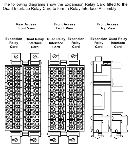
Power and relay wiring: The rated current of the power cable should be greater than the maximum load. If the relay cable is connected to an AC power source, a 5A fuse is required. The DC input card and relay interface card terminals support 2.5mm ² wires. When wiring, the power should be disconnected to avoid short circuits.
(3) Power configuration
The total power consumption of the system needs to be calculated through the "power budget table", depending on the sensor type, number of channels, and module configuration; When there are more than 8 catalytic control cards, it is recommended to supply power separately through the four relay interface card to avoid the backplane current exceeding the 8A limit.
Supports dual input of main power supply and backup battery, with diode isolation achieved through a DC input card. The backup battery needs to be compatible with 18-32V DC specifications.
Operation and maintenance process
(1) Basic operation (without engineering key)
Control card reset and selection: Short press the RESET/SET button to reset inactive alarms and clear peak display; Long press and hold for 1.5 seconds to select the control card, then use the up and down keys on the engineering card to select the channel; Press and hold for 5 seconds to perform an extended reset (clear maximum/minimum readings, reset STEL/LTEL timer).
Basic functions of the engineering card: It can view the catalytic sensor bridge current (BEAD mA key), alarm threshold (ALARMS key), sensor signal (SIGNAL key), and system clock (CLOCK key). Calibration, suppression, and other operations cannot be performed without a key, and the selection will be automatically canceled after 30 seconds of timeout.
(2) Engineering operation (requires inserting the engineering key to unlock)
Channel suppression (INHIBIT key): After selecting a channel, press the INHIBIT key to switch the suppression state. During suppression, the channel LED will remain amber and the relay will be locked in an inactive state to avoid false alarms during calibration or troubleshooting.
Calibration process
Zero calibration (ZERO key): Ensure that the sensor is in a gas free environment, press the ZERO key, wait for the signal to stabilize (message displays "STANBLE"), and then press the confirm key. The system will automatically set the current signal to zero. If the signal exceeds the range, an error will be displayed.
Range calibration (SPAN key): Suitable for calibrated sensors, press the SPAN key to set the target range concentration, introduce the corresponding concentration standard gas, confirm after the signal is stable, and the system updates the range parameters; The new sensor requires the "1st SPAN" key to perform the first range calibration and record the initial sensitivity for lifespan monitoring.
Alarm and Relay Testing: Press the ALARMS key to set the A1/A2/A3/SETL/LTEL threshold. After switching to "TEST" mode, simulate gas concentration changes by pressing the up and down keys to verify whether the alarm LED and relay actions are normal. During testing, be sure to release the suppression to trigger the external relay.
(3) Maintenance and troubleshooting
Regular maintenance: It is recommended to check the terminal fastening, LED status, sensor signal and alarm function every year. The catalytic sensor needs to be calibrated regularly (according to the sensor manual). When the sensitivity of the catalytic sensor drops below 50% of the initial value, the system displays "Lifetime Expired" and the sensor needs to be replaced.
Fault diagnosis: Identify the problem through the error codes displayed on the control card message (such as ER97 for EEPROM fault, ER87 for over range fault, ER83 for bridge current fault), and check the power supply, wiring, and sensor status using the "troubleshooting table". Hardware faults require replacement of the corresponding module.
Data recording: It can be connected to an RS232 printer through an engineering card, and long press the up and down keys to print single channel status or overall rack summary data, including sensor type, calibration date, alarm threshold, relay configuration, and other information.

Compliance and safety requirements
(1) Certification and Standards
Compliant with EN50054/57/58 (General Requirements and Performance for Combustible Gas Detection), EN50271 (Software and Digital Technology), EMC Directive 89/336/EEC (EN50270:1999), Low Voltage Directive 73/23/EEC (EN 61010-1), ATEX certification based on EC Type Examination Certificate BVS 04 ATEX G 001 X, suitable for Zone 2 hazardous areas (requiring tested enclosures).
- ABB
- General Electric
- EMERSON
- Honeywell
- HIMA
- ALSTOM
- Rolls-Royce
- MOTOROLA
- Rockwell
- Siemens
- Woodward
- YOKOGAWA
- FOXBORO
- KOLLMORGEN
- MOOG
- KB
- YAMAHA
- BENDER
- TEKTRONIX
- Westinghouse
- AMAT
- AB
- XYCOM
- Yaskawa
- B&R
- Schneider
- Kongsberg
- NI
- WATLOW
- ProSoft
- SEW
- ADVANCED
- Reliance
- TRICONEX
- METSO
- MAN
- Advantest
- STUDER
- KONGSBERG
- DANAHER MOTION
- Bently
- Galil
- EATON
- MOLEX
- DEIF
- B&W
- ZYGO
- Aerotech
- DANFOSS
- Beijer
- Moxa
- Rexroth
- Johnson
- WAGO
- TOSHIBA
- BMCM
- SMC
- HITACHI
- HIRSCHMANN
- Application field
- XP POWER
- CTI
- TRICON
- STOBER
- Thinklogical
- Horner Automation
- Meggitt
- Fanuc
- Baldor
- SHINKAWA
- Other Brands


