
TOSHIBA TOSBERT VF-A3 frequency converter
Equipment specifications:
Voltage level, power range, core application scenarios
200V level 0.4-55kW small and medium-sized motor drive (such as conveyor, fan)
400V level 0.75-75kW medium and large motor drive (such as pumps and compressors)
TOSHIBA TOSBERT VF-A3 frequency converter
Overview and Basic Equipment Information
Positioning: The official user manual for Toshiba TOSBERT VF-A3 series high-performance frequency converters, used to guide users in installation, operation, maintenance, and troubleshooting.
Equipment specifications:
Voltage level, power range, core application scenarios
200V level 0.4-55kW small and medium-sized motor drive (such as conveyor, fan)
400V level 0.75-75kW medium and large motor drive (such as pumps and compressors)
Equipment features:
High reliability: Built in current limiting, retry, soft stop, and instantaneous power-off protection functions to reduce the probability of tripping.
Easy to operate: keyboard style operation panel, supports memory commands, basic settings do not require stopping the machine to consult the manual.
Compact design: The research body integrates multiple protection functions, saving installation space.
Model coding rules: Taking "VFA3-2150P" as an example, the meanings of each part are as follows:
VFA3: Series Code (VF-A3 Series)
2: Voltage level (2=200V level, 4=400V level)
15: Capacity (15kW)
0: Special configuration (0=Standard)
P: Panel configuration (P=equipped with operation panel)
Installation and wiring specifications
1. Installation requirements
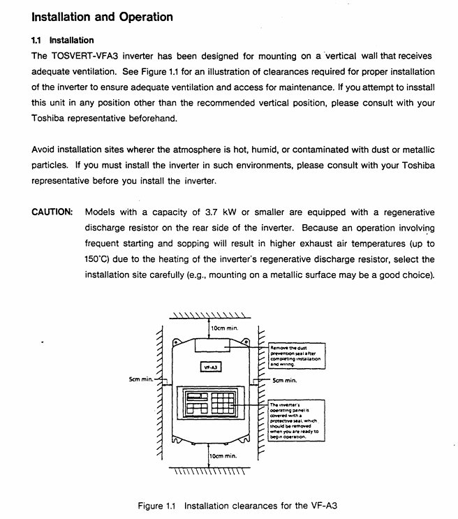
Installation method: Only supports vertical wall mounted installation. For non vertical installation, please consult a Toshiba representative.
Ventilation gap (Figure 1.1):
Top/bottom: minimum 10cm
Left and right sides: minimum 5cm
Environmental restrictions:
Temperature: -10 ℃~40 ℃ (up to 50 ℃ without casing)
Humidity: ≤ 90%, no condensation
Altitude: ≤ 1000m (3300ft)
Vibration: Acceleration ≤ 0.5G (20-50Hz), amplitude ≤ 0.1mm (50-100Hz)
Special note: Models with 3.7kW and below have a built-in regenerative discharge resistor on the back. Frequent start stop cycles can cause the exhaust temperature to reach 150 ℃. It is recommended to install it on a metal surface for heat dissipation.
2. Wiring process and specifications
Preparation before wiring:
Disconnect the main switch of the distribution panel and confirm that the "CHARGE" light of the frequency converter is off (to avoid electric shock).
Open the front cover: Pull forward and lift up (Figure 1.2).
Main circuit wiring (Figure 1.3):
Terminal Name Connection Object Precautions
L1/R, L2/S, L3/T 3-phase power input cannot be reversed to the motor end (T1/U, etc.), otherwise the equipment will be damaged
T1/U, T2/V, T3/W 3-phase motors require corresponding motor U, V, and W terminals
The grounding wire of the G/E system complies with Class 3 grounding specifications
R1/T1 (200V level), R38/R41 (400V level) control circuit power supply single-phase signal, ensuring independent power supply for the control circuit
Control circuit wiring:
Frequency setting signal: PP (10Vdc reference) RR(0-10Vdc/0-5Vdc)、IV(0-5Vdc/4-20mAdc), The type needs to be switched through JP1/JP2 jumper (Table 6.1).
Operation control signals: ST (preparation for operation), F (forward rotation), R (reverse rotation), JOG (jog), short circuit the corresponding terminal to CC to achieve the function.
Taboo:
Do not connect power factor compensation capacitors on the power side or motor end.
The control circuit (excluding FLA/FLB/FLC) needs to be insulated from the main circuit to avoid interference.
Operation process and core function settings
1. Operation panel and basic operations
Panel layout (Figure 2.1): including "PANEL CON" LED, MON (monitoring/setting switch), RUN/STOP (run/stop), frequency ± key, parameter setting key (WRT/READ/NEXT, etc.).
Simplify the operation process (trial run, recommended low-frequency startup):
Power ON: When the MCCB is closed, the monitor flashes "OFF" first and then displays "0.0".
Switch panel control: Press the "CTRL" key, and the "PANEL Control" LED will light up.
Set frequency:
Numerical keys: If set to 10Hz, press "1", "0", and "WRT" to display "10" and "FC" alternately.
± key: Long press "△" (increase)/"▽" (decrease), if set to 5.5Hz, press "WRT" to save.
Start/Stop: Press "RUN" to accelerate to the set frequency; Press' STOP 'to slow down and stop.
2. Core Function Settings
(1) Frequency and voltage characteristic settings
Maximum frequency (FH): 30-400Hz (1Hz step size), default 50Hz for 50Hz models and 60Hz for 60Hz models, cannot be modified during operation (requires shutdown).
Torque boost (ub): 0-30% (1% step size), default 3%, used to boost starting torque, excessive can cause overcurrent during startup.
Automatic torque boost (Rub): 0=off, 1=on, automatically adjusts voltage based on load current (Figure 3.4).
Fundamental frequency (uL): 25-400Hz (1Hz step size), set 50Hz for 50Hz motors and 60Hz for 60Hz motors (Table 3.1).
V/f mode (Pt.): 0=constant torque (conveyor), 1=variable torque (fan/pump, energy-saving) (Figure 3.6).
(2) Acceleration, deceleration, and braking control
Acceleration and deceleration time (ACC/DEC):
Range: 0.1-6000 seconds, supports 2 sets of time (ACC1/ACC2, DEC1/DEC2).
- OMRON
- ABB
- General Electric
- EMERSON
- Honeywell
- HIMA
- ALSTOM
- Rolls-Royce
- MOTOROLA
- Rockwell
- Siemens
- Woodward
- YOKOGAWA
- FOXBORO
- KOLLMORGEN
- MOOG
- KB
- YAMAHA
- BENDER
- TEKTRONIX
- Westinghouse
- AMAT
- AB
- XYCOM
- Yaskawa
- B&R
- Schneider
- KONGSBERG
- NI
- WATLOW
- ProSoft
- SEW
- ADVANCED
- Reliance
- TRICONEX
- METSO
- MAN
- Advantest
- STUDER
- DANAHER MOTION
- Bently
- Galil
- EATON
- MOLEX
- DEIF
- B&W
- ZYGO
- Aerotech
- DANFOSS
- Beijer
- Moxa
- Rexroth
- Johnson
- WAGO
- TOSHIBA
- BMCM
- SMC
- HITACHI
- HIRSCHMANN
- Application field
- XP POWER
- CTI
- TRICON
- STOBER
- Thinklogical
- Horner Automation
- Meggitt
- Fanuc
- Baldor
- SHINKAWA
- Other Brands
- UniOP
- KUKA
- Iba
- Beckhoff
-
 Basler BE1-25 Time Overcurrent Relay M1FA6PA4S0F
 -
 Basler SR4A2B05B3E Static Voltage Regulator
 -
 Basler DECS-200-2L Digital Excitation Control
 -
 Basler BE303280001 Control Transformer
 -
 Basler 9262103004 Voltage Regulator Board For Basler DECS-400
 -
 Basler ICRM-7 Inrush Current Reduction Module
 -
 Basler BE1-32R Power Relay
 -
 BASLER ELECTRIC KR4F VOLTAGE REGULATOR 9042600100 600V 50/60Hz
 -
 Basler 9222600101 Power Module
 -
 Basler SR8A-2B15B3A Static Voltage Regulator
 -
 BASLER BE1-87G G1E A1L A0N1P Generator Differential Relay w/ Reactor 9170818100
 -
Basler 9284900101 DECS Power Module
-
 Basler PRS250 Veri-Sync Relay
 -
 Basler BE 12296 001 Transformer
 -
 Basler 905970-104 Rev.M Voltage Regulator
 -
Basler BE1-87T Transformer Differential Relay
-
 Basler SR8A-2B15B3A Static Voltage Regulator
 -
 Basler SR32A2B05B3E Static Voltage Regulator
 -
 Basler SR4A-2B16B3A Static Voltage Regulator
 -
 Basler SR32A-2B13B3E Static Voltage Regulator
 -
 Basler KR4F Voltage Regulator 9042600100
 -
 Basler SSR 32-12 Static Voltage Regulator 400Hz
 -
 Basler CBS 212A Current Boost System
 -
 Basler MVC236 Manual Control Module
 -
Basler UFOV Protective Module 9040000100
-
 Basler SSR 125-12 Static Voltage Regulator
 -
 Basler SR4A2B10A3E Static Voltage Regulator
 -
 Basler BE1-25 Solid State Time Overcurrent Relay
 -
 Basler MVC 232 Manual Voltage Control Module
 -
Basler PRS 250 Veri-Sync Relay
-
 Basler UFOV 260A Under Frequency Over Voltage Relay
 -
 Basler RUL2098-10GC Load Relay
 -
 Basler 9 1049 04 100 PC Board
 -
Basler 125-12 Static Voltage Regulator
-
Basler PRS 250 Veri-Sync Relay
-
Basler 9185900102 SSR 125-12 Regulator
-
Basler BE12819001 Reactor
-
 Teradyne 535-100-00 Power Supply
 -
 Basler BE1-67 Directional OC Relay
 -
 Basler PRP110 Reverse Power Relay
 -
 Basler BE30631001 Isolation Transformer
 -
 Basler DECS-200-2L Digital Excitation Control
 -
 Basler BE1-47N Voltage Phase Sequence Relay
 -
 Basler AEC63-7 Analog Excitation Controller 220-277V
 -
Basler BE1-50/51B-107 Overcurrent Relay
-
 Basler Electric BE1‑32R BE1‑E1P‑BON0F Protective Relay
 -
Basler BE1-25 Solid State Time Overcurrent Relay M1EA6PA5S1F
-
 Basler MVC 232 Manual Voltage Control Module 90 37000 103 60VAC 55VDC
 -
Basler RAL6144-16GM Racer GigE Line Scan Camera
-
Basler SSR 63-12 Static Voltage Regulator
-
 Basler BE1-51A Overcurrent Relay
 -
Basler BE1-87T Solid State Protective Relay
-
Basler SR4A2B01B3A Static Voltage Regulator
-
 Basler SSR 32-12 Static Voltage Regulator
 -
 Basler TRR00696 Transformer 1KVA 115V
 -
 Basler DECS-100-B15 AVR Replacement
 -
Basler BE1-27 Under-Voltage Relay
-
 Basler ACA2000-50GM Interface Module
 -
 Basler AEC63-7 Analog Excitation Controller
 -
Basler PRS 250 Veri-Sync Relay
-
 Basler SR4A-2B15B3A Static Voltage Regulator
 -
Basler BE1-32R Power Relay
-
Basler SR8A-2B06B3E Static Voltage Regulator
-
Basler BE1-81 O/U Frequency Relay
-
 Basler BE1-51A-K2E-W6M-B1N0F Overcurrent Relay
 -
Basler BE1-851 Overcurrent Relay G3A1S1 – 48-125V AC/DC
-
 Basler BEI-51 Overcurrent Relay – NSN 5945-01-293-2363
 -
Basler Electric L301KC Protective Relay – L301KC
-
 Basler DECS-100-B15 Automatic Voltage Regulator – Generator AVR
 -
Basler SR4A-2B15B3A Static Voltage Regulator – SR4A2B15B3A
-
Basler UF 312 Under Frequency Protective Module – 9094700100
-
Basler Electric MVC 232 Manual Control Module – 60VAC 55VDC 20A
-
Basler PRS 250 Veri-Sync Relay – Generator Synchronizing Relay
-
 Basler DECS-100-A05 Digital Regulator Review
 -
 Basler AEM-2020 Analog Expansion Module Specs
 -
 Basler DECS-100-B15 Digital Excitation Specs
 -
Basler Electric 9125600106 Regulator Component
-
Basler BE1-51A-K1E-W6M-B1N0F Overcurrent Relay
-
 Basler MVC-301 MVC 300 Excitation Controller
 -
Basler SSR 32-12 Static Voltage Regulator
-
Basler 9-2849-00-101 Control Module
-
Basler BE1-51A Overcurrent Relay
-
 Basler BE1-51/27R Overcurrent Relay
 -
 Basler BE1-51 Overcurrent Relay
 -
 Basler SR8A-2B15B3A Static Voltage Regulator
 -
 Basler BE32965001 Transformer and Timer Board
 -
 Basler 9174700100 EL200-7 Excitation Limiter
 -
 Basler BE2000E AVR Voltage Regulator
 -
Basler BE1-87G Differential Relay
-
 Basler BE21834001 Generator Control Module
 -
Basler DECS-100-B15 AVR
-
 Basler D90 96801 100 PCB Card
 -
 Basler XR2002F Voltage Regulator (110 VAC, 48-480 Hz)
 -
 Basler SR8A-2B14B3A Regulator
 -
 Basler 9561500100 Module
 -
 Basler DECS-400 BE1-11 System
 -
 Basler DECS-100-B15 Excitation Control
 -
Basler SCP 210 Frequency Controller
-
Basler SR4A-2B15B3A Static Voltage Regulator
-
Basler BE1-32R Power Relay
-
 Basler PIA2400-17GM Power Interface Adapter
 -
 Basler MVC 232 Manual Voltage Control Module
 -
Basler SSR 32-12 Static Voltage Regulator
-
Basler 5MW AVR Generator Voltage Regulator
-
 Basler VR63-4B Voltage Regulator
 -
Basler DECS-100-A05 AVR for Engine Generator
-
Basler DECS-100-B15 Automatic Voltage Regulator
-
Basler BE1-32R Directional Power Relay
-
Basler BE1-87B Differential Relay
-
 Basler UFOV 260A Protective Module
 -
 Basler 9-2614-02-100 PCB Rev M
 -
Basler DECS-100-B15 Digital AVR
-
 Basler 9284900103 PS DECS-400N
 -
 Basler D4N3H1U Intertie Protection
 -
 Basler DECS-100-B15 A15 AVR
 -
 Basler KR4F Voltage Regulator
 -
 Basler BE26434 T14 Transformer
 -
 Basler SR8A-2B15B3A Regulator
 -
 Westinghouse 774B472A12 AR Relay
 -
Basler DECS-100-B15 AVR
-
Basler XR2002F Regulator 110V
-
Basler SR125-E Static Regulator
-
Basler SSR 125-12 Regulator
-
Basler MOC2599 Motor Pot
-
 Basler BE1-DFPR Feeder Relay
 -
 Basler CBS 305 Current Boost
 -
Basler BE1-25 AutoSync
-
Basler MVC 300 Voltage Control


