TOSHIBA TOSBERT VF-A3 frequency converter
Equipment specifications:
Voltage level, power range, core application scenarios
200V level 0.4-55kW small and medium-sized motor drive (such as conveyor, fan)
400V level 0.75-75kW medium and large motor drive (such as pumps and compressors)
Mode: 0=linear, 1=non-linear 1 (slow acceleration at low torque), 2=non-linear 2 (slow acceleration at high speed) (Figure 3.8).
DC injection braking (dbF/dbu/dbt):
Starting frequency (dbF): 0-10Hz, braking voltage (dbu): 0-20%, braking time (dbt): 0-5 seconds, used for precise positioning (Figure 3.27).
Regenerative braking (Pb):
Applicable scenarios for Pb setting function
0 normal load without regenerative braking (or using regenerative discharge unit)
1. There is regenerative braking, no resistance overload detection, and moderate inertia load
2. There is regenerative braking and resistance overload detection for large inertia loads (such as centrifuges)
(3) Multi speed and special operation
Multi speed operation (S1-S7): 7 speeds are achieved through the combination of SS1/SS2/SS3 terminals, with a frequency range from the lower limit frequency (LL) to the upper limit frequency (UL), and can be controlled by panel or external signals (Table 3.7).
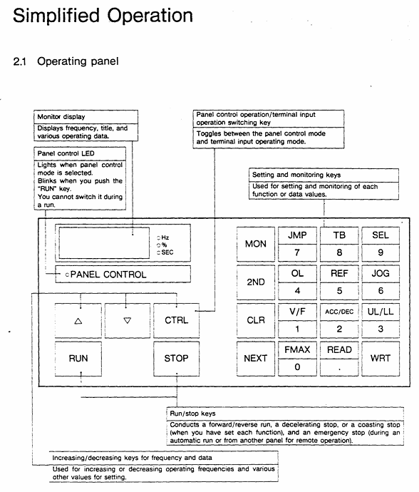
Jog operation (JOG): frequency 0-20Hz (0.1Hz step size), only starts when stopped, press the "RUN" button to run, release to stop (Figure 3.21).
Frequency jump (FJ1-FJ3): 3 jump points, set the jump frequency and width to avoid load resonance (Figure 3.24).
3. Status monitoring and fault reset
Operation/shutdown monitoring: Press the "NEXT" button to cycle through the status (Table 3.2), such as "60.0"=operating frequency 60Hz, "PSO. 0"=overvoltage limit activation, "OC"=overcurrent detection.
Fault monitoring: When tripping, press "NEXT" to check the fault status (such as frequency, current, voltage), and support tracing the last 4 faults (Table 3.4).
Fault reset:
Panel reset: Press "CLR"+"WRT".
External reset: Short circuit the RST-CC terminal (Figure 4.9).
Troubleshooting and Maintenance
1. Fault codes and solutions (Table 9.1)
Meaning of fault code and solution measures
OC1 acceleration overcurrent 1. Increase ACC time; 2. Reduce UB settings; 3. Check if there is a sudden change in the load
OH frequency converter overheating 1. Check the cooling fan; 2. Confirm that the ambient temperature is ≤ 40 ℃; 3. Clean the heat dissipation channel
EF load terminal grounding fault 1. Check the insulation of the motor and output circuit; 2. Check the grounding short circuit point
EEP EEPROM abnormality 1. Restart the power supply; 2. If ineffective, repair/replace EEPROM
2. Regular maintenance and storage
Regular inspection (every 3-6 months):
Terminal screws: Tighten loose screws to prevent poor contact.
Line inspection: Check if the wire crimping point is overheated (discolored) and if the insulation is damaged.
Dust removal: Use a vacuum cleaner to clean the ventilation openings and printed circuit board dust to avoid overheating.
Insulation test: Use a 500V megohmmeter to test the insulation of the main circuit. The motor needs to be tested after disconnecting the frequency converter.
Storage requirements:
Environment: Dry, dust-free, non corrosive gas, temperature -10-40 ℃.
Activation: Long term storage (>2 years) requires power on every 2 years; After removing the storage, the motor needs to be powered on for at least 5 hours before running.

Optional accessories and warranty terms
1. Optional accessories (Table 7.1/7.2)
Type Accessory Name Model Example Function
External installation of input reactor PFL2012-2100 improves power factor and suppresses harmonics
External installation of regenerative discharge resistor PBR3-2055 enhances braking effect, suitable for large inertia loads
Built in multi option printed circuit board VF3X-0888B supports RS-232C communication, BCD code input, etc
External installation of PANEL-KIT (1M/3M/5M) remote control panel, including 1/3/5 meter cable
2. Warranty terms
Warranty period: 12 months after delivery.
Warranty expiration situation:
Unauthorized maintenance/modification of equipment.
Damage caused by vibration/impact during transportation/installation.
Force majeure events such as fires, floods, lightning strikes, and abnormal power grid voltage.
Used for designated purposes of non industrial frequency converters.
Acceptance requirements: After opening the box, check that the equipment is undamaged and the model is consistent with the order. If there are any problems, immediately contact a Toshiba representative.
Key issues
Question 1: What are the space and environmental restrictions that must be followed when installing the TOSBERT VF-A3 frequency converter? What are the consequences of ignoring these restrictions?
Answer:
Restrictions that must be followed:
Installation method: Only supports vertical wall mounting, non vertical installation requires prior consultation with Toshiba representatives.
Ventilation gap: minimum 10cm at the top/bottom, and minimum 5cm on both sides to ensure smooth heat dissipation.
Environmental parameters: temperature -10 ℃~40 ℃ (≤ 50 ℃ without casing), humidity ≤ 90% (no condensation), altitude ≤ 1000m, vibration acceleration ≤ 0.5G (20-50Hz)/amplitude ≤ 0.1mm (50-100Hz).
Special models: Models with 3.7kW and below have regenerative discharge resistors on the back, and the exhaust temperature can reach 150 ℃. It is recommended to avoid installing on flammable surfaces and choose metal surfaces for heat dissipation.
- ABB
- General Electric
- EMERSON
- Honeywell
- HIMA
- ALSTOM
- Rolls-Royce
- MOTOROLA
- Rockwell
- Siemens
- Woodward
- YOKOGAWA
- FOXBORO
- KOLLMORGEN
- MOOG
- KB
- YAMAHA
- BENDER
- TEKTRONIX
- Westinghouse
- AMAT
- AB
- XYCOM
- Yaskawa
- B&R
- Schneider
- Kongsberg
- NI
- WATLOW
- ProSoft
- SEW
- ADVANCED
- Reliance
- TRICONEX
- METSO
- MAN
- Advantest
- STUDER
- KONGSBERG
- DANAHER MOTION
- Bently
- Galil
- EATON
- MOLEX
- DEIF
- B&W
- ZYGO
- Aerotech
- DANFOSS
- Beijer
- Moxa
- Rexroth
- Johnson
- WAGO
- TOSHIBA
- BMCM
- SMC
- HITACHI
- HIRSCHMANN
- Application field
- XP POWER
- CTI
- TRICON
- STOBER
- Thinklogical
- Horner Automation
- Meggitt
- Fanuc
- Baldor
- SHINKAWA
- Other Brands


