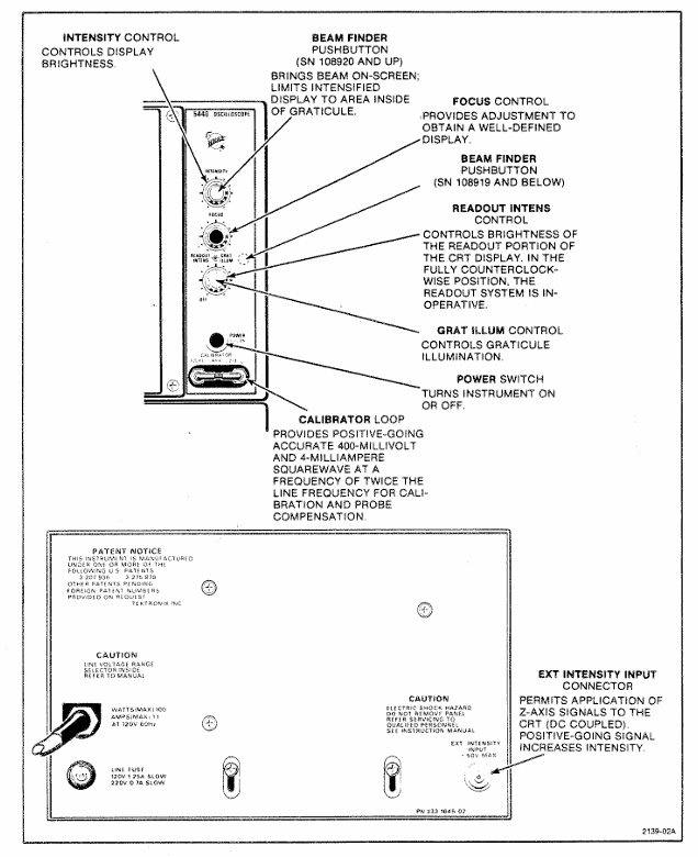
Tektronix 5440 oscilloscope
Frequency 1. Obtain the period (T) by measuring the time period method; 2. Frequency=1/T Example: Period 0.5ms, Frequency=1/0.5ms=2kHz
Rising time (10% -90% point) 1. Connect the signal, set Volts/Div and Variable to display 5 vertical divisions; 2. Adjust the trigger to obtain stable display, set Sec/Div to 10% -90% point display<8 divisions; 3. Measure the horizontal division of two points; 4. Result=Division value x Sec/Div Example: 4 divisions x 1 μ s/Div=4 μ s

Specification parameters
1: Vertical amplifier specifications
Additional information on characteristic performance requirements
Bandwidth (6-degree reference) DC to at least 85MHz (067-0680-00 calibration fixture); DC to at least 50MHz (calibrated 5A48)-
Rise time (6 divisions reference) 7ns or less (calibrated 5A48)-
Distortion (6-degree reference) 5% or less (067-0680-00 calibration fixture); 4% or less (calibrated 5A48)-
The influence of position on distortion ± step response signal deviation does not exceed ± 5% (trajectory deviation from the center of the scale does not exceed 1 division)-
Within ± 0.5 divisions of the center of the vertical center scale-
Delay line length 140ns-
Chopping rate 50kHz (+50% -30%), conducting in 3 μ s and turning off in 2 μ s-
Alternating rate: scan every two times-
Table 2: Specifications of Horizontal Amplifier and Z-axis Amplifier
Performance requirements for amplifier type characteristics
Horizontal amplifier bandwidth DC to at least 2MHz (8-division signal reference); At least 20kHz at the low frequency end
The Z-axis amplifier inputs a voltage of+5V to switch the CRT beam from off to on; -5V switches the beam from on to off
Available frequency range DC to 2MHz
Input impedance (resistance) 10k Ω
Table 3: Power, Environment, and Physical Specifications
Category Characteristics Performance Requirements
Power input voltage (RMS) nominal 100V, 110V, 120V, 200V
Input frequency adapted to standard power frequency
Maximum 100W at 120V AC and 60Hz input power
Fuse 120V AC with 1.25A slow melting; 240V AC with 0.7A slow melting
Environmental working temperature: 0 ° C to+50 ° C
Storage temperature -40 ° C to+70 ° C
Working altitude up to 15000 feet
Storage altitude up to 50000 feet
Physical weight 25lbs (11kg)
Panel and shell anodized aluminum panel (gray vinyl coated frame), blue vinyl coated shell
Scale dial 8 × 10 divisions, 1.22cm/division, standard white internal scale line, optional black
Installation and maintenance
(1) Rack installation
Requirement: Suitable for 19 inch standard racks (Universal, EIA, RETMA, Western Electric hole positions), with a minimum vertical space of 5-1/4 inches and an additional 1/4 inch heat dissipation space above and below; Front rail spacing ≥ 17-5/8 inches (unthreaded) or 17-3/4 inches (tapped); The gap between the rear and the rack enclosure is ≥ 2 inches.
Sliding rail installation: The sliding rail is divided into left and right components (marked LH/RH), with the fixed section installed on the front and rear rails of the rack, the chassis section pre installed with instruments, and the middle section connecting the two; During installation, it is necessary to align horizontally to avoid exchanging left and right (which may cause the safety lock to fail and cause the instrument to slide). The front panel needs to be fixed with 10-32 screws (the rack needs to correspond to the hole position).
Maintenance: The slide rail does not require lubrication, and the dark coating on the sliding parts is permanently lubricated.
(2) Plugin installation and maintenance
Installation: Align the upper and lower slots of the plug-in with the cabin guide rail, and push it into the lock; It can be plugged and unplugged with power, without filling all cabins, only installing the required measuring plugs is needed.
Calibration: After the display unit is calibrated according to the instructions, the vertical/horizontal gain is standardized. The plug-in can be interchanged between cabins without the need for readjustment, but the basic calibration of the plug-in itself needs to be checked to ensure measurement accuracy (refer to the plug-in manual).
(3) Safety regulations
Maintenance safety: Only qualified personnel are allowed to carry out repairs, and individual repairs are prohibited (emergency personnel must be provided); Live maintenance should avoid touching exposed connections/components, and disconnect the power supply before dismantling panels, welding, or replacing components.
Power safety: The power supply must meet the RMS voltage between phase lines and between phase lines and ground ≤ 250V, and the grounding conductor of the power line must be reliably grounded.
Performance check
(1) Testing equipment requirements (key equipment as follows)
Equipment Name Performance Requirements Application Scenarios
DC voltmeter range 0-200V (accuracy 0.1%); 0-3000V (accuracy 1%) low/high voltage power supply inspection and adjustment
Calibration generator amplitude calibration 10mV-1V (accuracy ± 0.25%, 1M Ω load), square wave output gain inspection and adjustment
Timing generator outputs 5ns and 10ns markers (accuracy ± 1%) for scanning timing inspection (5ns, 10ns)
- ABB
- General Electric
- EMERSON
- Honeywell
- HIMA
- ALSTOM
- Rolls-Royce
- MOTOROLA
- Rockwell
- Siemens
- Woodward
- YOKOGAWA
- FOXBORO
- KOLLMORGEN
- MOOG
- KB
- YAMAHA
- BENDER
- TEKTRONIX
- Westinghouse
- AMAT
- AB
- XYCOM
- Yaskawa
- B&R
- Schneider
- Kongsberg
- NI
- WATLOW
- ProSoft
- SEW
- ADVANCED
- Reliance
- TRICONEX
- METSO
- MAN
- Advantest
- STUDER
- KONGSBERG
- DANAHER MOTION
- Bently
- Galil
- EATON
- MOLEX
- DEIF
- B&W
- ZYGO
- Aerotech
- DANFOSS
- Beijer
- Moxa
- Rexroth
- Johnson
- WAGO
- TOSHIBA
- BMCM
- SMC
- HITACHI
- HIRSCHMANN
- Application field
- XP POWER
- CTI
- TRICON
- STOBER
- Thinklogical
- Horner Automation
- Meggitt
- Fanuc
- Baldor
- SHINKAWA
- Other Brands


