
Westinghouse WGen9500c portable generator
Power specification: 120/240V single-phase AC, frequency 60Hz, speed 3600rpm, voltage stability range 230-250V, frequency stability range 58-62Hz, suitable for most household and industrial equipment
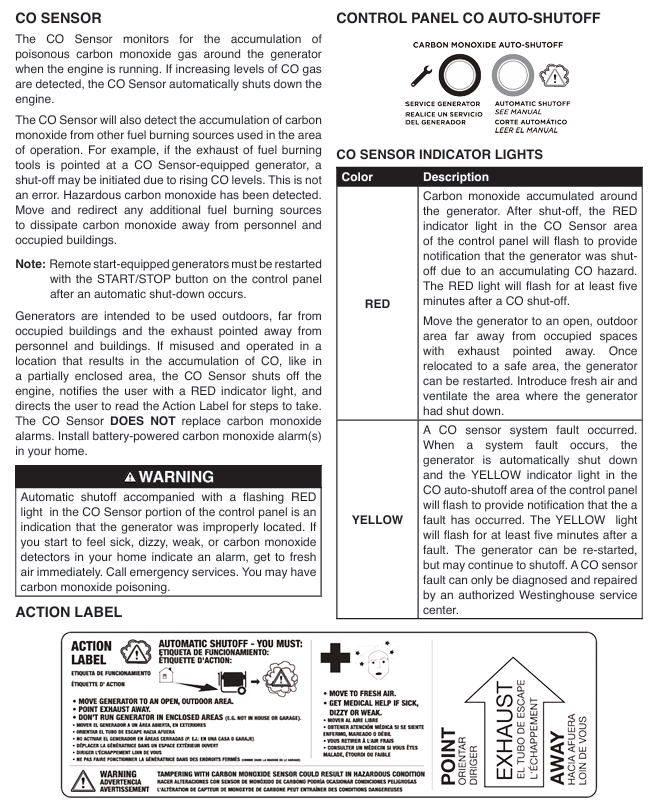
The CO alarm indicator light (red) lights up when the CO concentration exceeds the standard. At the same time, the generator needs to be stopped and moved to a ventilated area. After checking the environment, it can be restarted
Safety operation standards (including risk avoidance)
1. Environment and placement safety
Core requirements for placement:
Only use in fully open and well ventilated outdoor areas, at least 20 feet (about 6 meters) away from doors, windows, ventilation openings, tents, etc., to prevent carbon monoxide emissions from entering indoors.
Place on a hard, horizontal surface, avoiding tilting (angle ≤ 5 °), to prevent fuel leakage or uneven oil lubrication from causing engine wear.
At least 5 feet (about 1.5 meters) of heat dissipation space should be reserved around the fuselage, away from flammable materials such as hay, wood, paint, gasoline, etc. The exhaust port should face unmanned areas.
Environmental limitations and responses:
Operating temperature range: 5 ° F (-15 ° C) to 122 ° F (50 ° C). If it is below -15 ° C, it is necessary to replace the winter specific oil (5W-30) and keep the battery warm (to avoid power loss).
Prohibited scenarios: rainy, snowy, or damp ground (to prevent electric shock); Dust and corrosive gases (such as salt spray at the seaside and chemical plant areas) can easily cause component corrosion and blockage.
Extreme weather: In rainstorm days, a temporary canopy (not sealed, ensure ventilation) shall be built to avoid rain splashing the engine and control panel.
2. Fuel safety operation
Preparation before refueling:
Turn off the engine and wait for at least 2 minutes for it to cool down (the exhaust pipe temperature can reach over 400 ℃, which can easily ignite the fuel).
Clean the oil and dust around the fuel tank cap to prevent impurities from entering the fuel tank; Prepare a qualified fuel can and do not pour it directly from a bucket.
Refueling operation specifications:
Slowly add fuel, with the fuel level not exceeding the red limit ring inside the fuel tank (with 5-10% expansion space reserved), to avoid fuel spillage during high temperatures.
If fuel overflows, immediately wipe it clean with a dry cloth and wait for the fuel to completely evaporate before starting the engine (do not ignite immediately).
Fuel storage and handling:
Backup fuel should be stored in a compliant fuel container, in a well ventilated, cool, and away from sources of ignition. The storage time should not exceed 3 months (with the addition of fuel stabilizers, it can be extended to 6 months).
Degraded fuel must be handed over to professional institutions for recycling, and it is prohibited to dump it indiscriminately (which pollutes the environment and is flammable).
Forbidden operation: Do not refuel while the engine is running; Do not use fuel to clean the body or components; Do not place fuel containers on the generator or near heat sources.
3. Electricity safety regulations
Extension cable selection:
Outdoor dedicated, undamaged, and well grounded three core cables must be used, and the cable specifications must match the load:
20A load (such as small electric tools): Use a 12 gauge cable with a length ≤ 50 feet; 14 gauge cable, length ≤ 25 feet.
30A load (such as 3kW air conditioner): Use 10 gauge cable with a length ≤ 50 feet; Number 8 gauge cable, length ≤ 100 feet.
50A load (if multiple devices are powered simultaneously): Use gauge 6 cable with a length ≤ 50 feet.
It is prohibited to use two core ungrounded cables, damaged cables, or multiple cables connected in series (which are prone to heating and leakage).
Load access principle:
Before starting, all loads must be disconnected to avoid overload triggering protection during startup.
After the generator runs stably (no-load for 3-5 minutes), connect high-power devices (such as air conditioning and water pumps) first, and then connect low-power devices (such as lights and mobile phone chargers), with a total operating power of ≤ 9500W and a total starting power of ≤ 12500W.
The starting power of inductive loads (motors) is 3-5 times the operating power and needs to be calculated separately to avoid multiple inductive loads starting simultaneously (such as a 3kW air conditioner and a 2kW water pump, the starting power may exceed 12500W).
Grounding and grid connection requirements:
The neutral wire of the generator is connected to the metal casing of the machine body and does not require additional grounding; If it is necessary to connect to the household fixed power distribution system, a certified electrician must install an automatic transfer switch (direct grid connection is prohibited to avoid reverse power transmission to the grid).
When connecting metal shell equipment (such as power tools, water pumps), ensure that the equipment is well grounded to avoid electric leakage and shock.
Emergency handling of faults: If equipment trips, heats up, or emits odors during power consumption, immediately disconnect the load, shut down the generator, and troubleshoot (such as overload or short circuit) before use; If there is electric leakage or shock, immediately cut off the power supply and seek medical attention in severe cases.
- OMRON
- ABB
- General Electric
- EMERSON
- Honeywell
- HIMA
- ALSTOM
- Rolls-Royce
- MOTOROLA
- Rockwell
- Siemens
- Woodward
- YOKOGAWA
- FOXBORO
- KOLLMORGEN
- MOOG
- KB
- YAMAHA
- BENDER
- TEKTRONIX
- Westinghouse
- AMAT
- AB
- XYCOM
- Yaskawa
- B&R
- Schneider
- KONGSBERG
- NI
- WATLOW
- ProSoft
- SEW
- ADVANCED
- Reliance
- TRICONEX
- METSO
- MAN
- Advantest
- STUDER
- DANAHER MOTION
- Bently
- Galil
- EATON
- MOLEX
- DEIF
- B&W
- ZYGO
- Aerotech
- DANFOSS
- Beijer
- Moxa
- Rexroth
- Johnson
- WAGO
- TOSHIBA
- BMCM
- SMC
- HITACHI
- HIRSCHMANN
- Application field
- XP POWER
- CTI
- TRICON
- STOBER
- Thinklogical
- Horner Automation
- Meggitt
- Fanuc
- Baldor
- SHINKAWA
- Other Brands
- UniOP
- KUKA
- Iba
- Beckhoff
-
 Basler D90 96801 100 PCB Card
 -
 Basler XR2002F Voltage Regulator (110 VAC, 48-480 Hz)
 -
 Basler SR8A-2B14B3A Regulator
 -
 Basler 9561500100 Module
 -
 Basler DECS-400 BE1-11 System
 -
 Basler DECS-100-B15 Excitation Control
 -
 Basler SCP 210 Frequency Controller
 -
 Basler SR4A-2B15B3A Static Voltage Regulator
 -
 Basler BE1-32R Power Relay
 -
 Basler PIA2400-17GM Power Interface Adapter
 -
 Basler MVC 232 Manual Voltage Control Module
 -
 Basler SSR 32-12 Static Voltage Regulator
 -
 Basler 5MW AVR Generator Voltage Regulator
 -
 Basler VR63-4B Voltage Regulator
 -
 Basler DECS-100-A05 AVR for Engine Generator
 -
 Basler DECS-100-B15 Automatic Voltage Regulator
 -
 Basler BE1-32R Directional Power Relay
 -
 Basler BE1-87B Differential Relay
 -
 Basler UFOV 260A Protective Module
 -
 Basler 9-2614-02-100 PCB Rev M
 -
Basler DECS-100-B15 Digital AVR
-
 Basler 9284900103 PS DECS-400N
 -
 Basler D4N3H1U Intertie Protection
 -
 Basler DECS-100-B15 A15 AVR
 -
 Basler KR4F Voltage Regulator
 -
 Basler BE26434 T14 Transformer
 -
 Basler SR8A-2B15B3A Regulator
 -
 Westinghouse 774B472A12 AR Relay
 -
Basler DECS-100-B15 AVR
-
Basler XR2002F Regulator 110V
-
Basler SR125-E Static Regulator
-
 Basler SSR 125-12 Regulator
 -
 Basler MOC2599 Motor Pot
 -
 Basler BE1-DFPR Feeder Relay
 -
 Basler CBS 305 Current Boost
 -
 Basler BE1-25 AutoSync
 -
 Basler MVC 300 Voltage Control
 -
 Basler BE3-25A AutoSync
 -
 Basler KR7FF Static Regulator
 -
 Basler 90-49000-100 Regulator
 -
 Basler 880 kVA Dry Type Transformer Specs
 -
 Basler Electric BE1-25 Sync-Check Relay Specs
 -
 Basler SSR 125-12 Voltage Regulator Specs
 -
 Basler Electric BE1-851 Overcurrent Relay Review
 -
Basler Electric 149D930G02 Control Sub-Assembly
-
 Basler Electric BE1-81O/UT Frequency Relay Specs
 -
 Basler Electric BE1-51/27C Overcurrent Relay
 -
 Basler Electric 149D956G02 Industrial Component
 -
Basler Electric BE1-51A Overcurrent Relay Specs
-
 Basler Electric BE1-40Q Loss of Excitation Relay
 -
 Basler DECS-200 Excitation Control System
 -
 Basler DECS-200 Voltage Regulator 56-277V AC / 125V DC
 -
Basler BE1-87T Transformer Differential Relay
-
 Basler RDP-110-S1 Protection Relay
 -
 Basler BE1-700V Digital Protective Relay
 -
 Basler BE1-951 Overcurrent Protection System
 -
 Basler DECS-300 Digital Excitation Control
 -
 Basler DECS-200 Digital Excitation Control
 -
 Basler DECS-200-1C Excitation Control System
 -
Basler DECS-200-1L Digital Excitation Control
-
 Basler Electric BE1-GPS Generator Protection System
 -
Basler Electric DECS-200-1C Digital Excitation Controller
-
 Basler Electric DECS125-15 Excitation Control with Power Module
 -
 Basler Electric BE1-87G Differential Relay
 -
 Basler Electric BE1-11 Protection System I5A3M2P2N0EA00
 -
Basler Electric DECS-200-1C Excitation Control System
-
Basler Electric BE1-11g Generator Protection Relay
-
Basler Electric DECS 125-15-B2C1 V2.0.9 Excitation Control
-
 Basler Electric BE1-81O/UT3ED1JA7N2F Frequency Relay
 -
Basler Electric BE1-81O/UT3EE1YB7N1F Frequency Relay
-
 Basler Electric DECS-200-1L Digital Excitation Control System
 -
Basler DECS125-15-B2C1 Excitation Control
-
 Basler 9507900205 SSR Retrofit Voltage Regulator
 -
 Basler BE2000E Digital Voltage Regulator
 -
 Basler BE1-GPS Generator Protection System
 -
Basler DECS-250-CN1CN1N Digital Excitation Control
-
 Basler DGC-2020 Genset Controller
 -
 Basler BE1-81O UT3ED1LA7N0F Frequency Relay (Variant)
 -
 Basler BE1-81O UT3EE1YA9S0F Frequency Relay (Variant)
 -
Basler BE1-81O Over/Under Frequency Relay
-
Basler DECS125-15 Digital Excitation Control
-
Basler Electric BE1-951 Overcurrent Protection System
-
 Basler Electric BE1-700V Digital Protective Relay
 -
 Basler Electric APR63-5 Automatic Voltage Regulator
 -
Basler Electric BE1-851 Overcurrent Protection System
-
Basler Electric DECS-250-LN1SN1N Excitation Control
-
 Basler Electric BE1-87T Transformer Differential Relay
 -
Basler Electric DECS-200-1L Excitation Control System
-
 Basler Electric 9310300100 DECS-300 Excitation Control
 -
 Basler Electric SSE-N 125-4.5KW Shunt Exciter Regulator
 -
 Basler Electric DGC-2020HD-5NS1DNSBA Genset Controller
 -
Basler Electric BE1-81-O/UT3EE1JB7N1F Frequency Relay
-
Basler Electric BE1-81T1EE1WA0N1F Frequency Relay
-
 Basler Electric BE1-25M1EA6PN5R1F Sync-Check Relay
 -
 Basler Electric BE1-GPS Generator Protection System
 -
Basler Electric DECS-250-LN1SN1N Excitation Control Rev V
-
 Basler Electric DECS-250-CN2CN1N Excitation Control
 -
Basler Electric BE1-50/51B-207 Overcurrent Relay
-
Basler Electric DECS-300-C0N0 Excitation Control System
-
Basler Electric DECS-200 Digital Excitation Control System
-
Basler Electric DECS-250-LN1CN1N Excitation Unit
-
Basler Electric DECS-250 LN2SA1D Excitation Unit Specs
-
Basler Electric BE1-87T Transformer Relay Review
-
Basler Electric BE1-11 Protection System
-
Basler Electric BE1-GPS100-E4N1H1N Protection System
-
 Allen-Bradley 442G-MABH-R Safety Module
 -
 Beckhoff CX1030-0111 PLC Assembly Profile
 -
 FANUC IC693CPU364 PLC Module
 -
 Orange Denmark Type 200816 220 PLC Specs
 -
 OMRON C200H-SNT31 Sysmac PLC Module
 -
 Allen Bradley 20AB022A3AYNANC0 PowerFlex 70
 -
 OMRON C200HW-PCU01 Position Control Unit
 -
 ABB AO845A-eA Analog Output Module
 -
 OMRON CJ1M-CPU22 CPU Unit
 -
 Allen Bradley 100-E265ED11 Contactor
 -
 Honeywell 51304511-100 Interface Module
 -
 SOLEXY BXF3S0101N0018 Gateway Module
 -
 OMRON CJ2H-CPU65 CPU Unit
 -
 Automation Direct GS2-45P0 AC Drive
 -
 M68-2000 2-Axis Motion CNC Controller
 -
 OMRON CJ1M-CPU11 V3.0 PLC CPU Unit
 -
 OMRON CJ1W-NC413 4-Axis Positioning Controller
 -
 OMRON 3G2A3-PRO16 Programming Console HMI
 -
 Siemens 3VT8440-2AA04-2GA2 Molded Case Circuit Breaker
 -
 Siemens 3RT5045 Contactor Series
 -
 OMRON C200HS-CPU01-E SYSMAC PLC Controller
 -
 OMRON C500-NC103-E Positioning Control Unit
 -
 OMRON CJ1W-TC001 Temperature Control Unit


