Allen Bradley 1734 series POINT I/O common terminal module and voltage terminal module
Common Terminal Module (1734-CTM/CTMK): Used to expand the common terminal wiring capability of POINT I/O modules, supporting centralized management of common lines for 8-channel high-density I/O modules. The suffix "K" is the conformal coating version (moisture-proof/corrosive environment), with specifications consistent with the uncoated version.
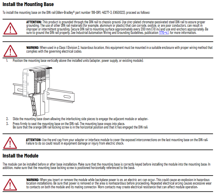
3. Install Removable Terminal Block (RTB)
Module matching 1734-RTB (detachable terminal block), supports wire free replacement of base, installation steps:
Terminal block positioning: Insert the RTB handleless end (with arc-shaped buckle) into the base and rotate it to lock (hear a "click" sound).
Handle fixation: If the I/O module has been installed, fasten the RTB handle onto the module to ensure that the terminal block is stable; When disassembling, simply pull the handle upwards without removing the wiring.
Special terminal block operation:
1734-RTBS/RTB3S: Use a 3mm diameter screwdriver (1492-N90) to insert into the opening at a 73 ° angle and gently push up to lock/unlock the wiring.
1734-TOPS/TOP3S: Insert the screwdriver into the opening at a 97 ° angle to avoid damaging the terminals.

(3) Wiring guidance: Terminal definition and typical scenarios
The module needs to be used in conjunction with POINT I/O modules, and the wiring needs to be disconnected first. The key specifications are as follows:
1. Terminal definition
1734-CTM (Common Terminal Module): The terminals are divided into "Common 0-7", corresponding to the common end of the 8-channel I/O module (such as the power common line of the digital module), which centrally manages the common line and reduces wiring redundancy.
1734-VTM (Voltage Terminal Module): The terminals are divided into "Voltage out 0~7" (voltage output) and "Common 0~7" (common terminal), providing power distribution for on-site equipment. The output voltage needs to be matched with an external power source (10~28.8V DC or 120/240V AC).
2. Typical wiring scenarios
The document provides wiring diagrams for four core scenarios (Figures 4 to 7), with key examples as follows:
Leakage type input wiring (1734-IB8 module+CTM/VTM): The "signal terminal" of the 2-wire/3-wire proximity sensor is connected to the input terminal of the I/O module, the "power terminal" is connected to the "Voltage out" of the VTM, and the "common terminal" is connected to the "Common" of the CTM, achieving separate management of power and common terminals.
Source type output wiring (1734-OB8 module+CTM): The "positive pole" of the actuator (such as indicator lights, relays) is connected to the output terminal of the I/O module, and the "negative pole" is centrally connected to the "Common" of the CTM, simplifying multi device common terminal wiring.
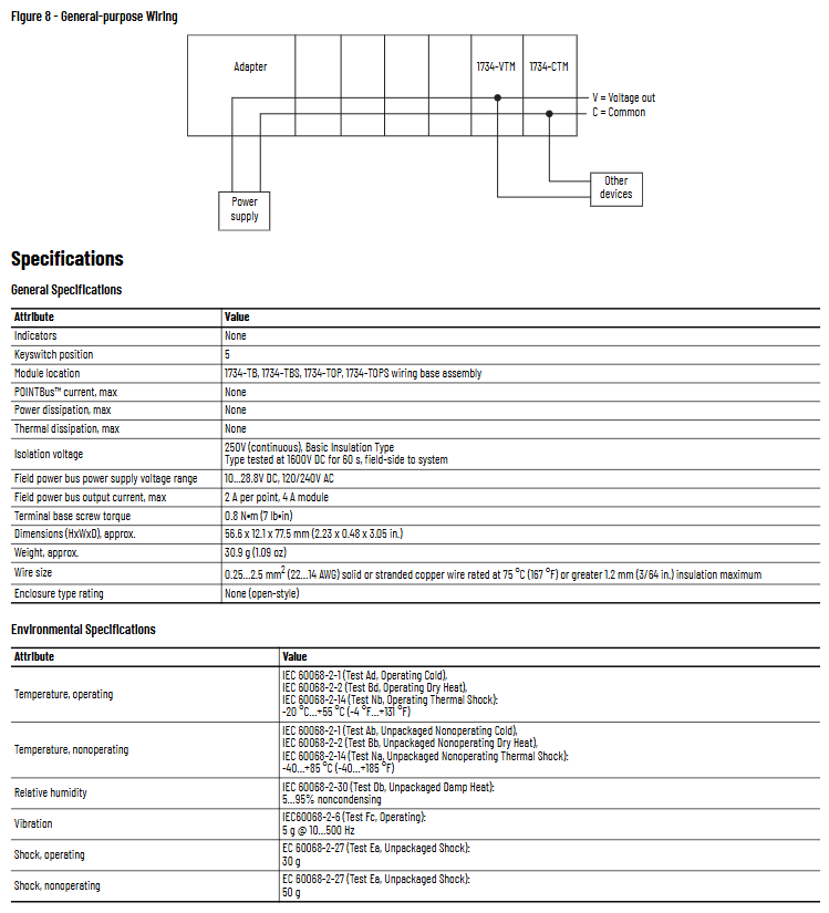
Universal wiring (adapter+CTM/VTM): VTM connects to an external power source to distribute voltage to other devices; CTM connects to the adapter's common end, achieving the aggregation of multiple module common lines and avoiding duplicate wiring.
3. Wiring parameters
Wire specifications: Supports solid or stranded copper wire of 0.25~2.5mm ² (22~14 AWG), with a maximum insulation thickness of 1.2mm (3/64 inches), and a rated temperature of ≥ 75 ° C (167 ° F).
Terminal torque: The tightening torque of the base screw is 0.8 N · m (7 lb · in), excessive tightening can damage the terminal.

(4) Technical parameters: Electrical and environmental specifications
1. General parameters
Parameter values
No indicator light
Key switch position 5
Adaptation base 1734-TB/TBS, 1734-TOP/TOPS
POINT Bus maximum current none
Maximum power consumption/heat dissipation none (only terminal expansion, no active components)
Isolation voltage 250V AC (continuous), 1600V DC (60 second test, on-site system side)
On site power bus voltage 10~28.8V DC, 120/240V AC
The maximum output current of the on-site power bus is 2A per point and 4A per module
The dimensions (height x width x depth) are approximately 56.6 x 12.1 x 77.5mm (2.23 x 0.48 x 3.05 inches)
Weight approximately 30.9g (1.09 ounces)
2. Environmental parameters
Parameter standards and numerical values
Working temperature -20 ° C~+55 ° C (-4 ° F~+131 ° F), in accordance with IEC 60068-2-1/2/14
Non working temperature -40 ° C~+85 ° C (-40 ° F~+185 ° F), in accordance with IEC 60068-2-1/2/14
Relative humidity of 5%~95% (non condensing), in accordance with IEC 60068-2-30
Vibration (working) 5g @ 10~500Hz, in accordance with IEC 60068-2-6
Impact (working) 30g, compliant with IEC 60068-2-27
50g impact (non working), in accordance with IEC 60068-2-27
3. Authentication information
C-UL-US certification: UL listed industrial control equipment, suitable for the United States and Canada; Certification for Class I Zone 2 (Groups A/B/C/D) Hazardous Areas (UL Document E194810).
UK and CE certification: VTM/VTMK complies with UK Regulation 1101 of 2016 and EU EMC Directive 2014/35/EU (EN 61131-2); All modules comply with the EU 2011/65/EU RoHS Directive (EN IEC 63000).
Moroccan certification: VTM/VTMK complies with Moroccan Ministerial Decree No. 6404-15.
(5) Module dismantling and maintenance
Dismantling process: The module, adjacent module on the right side, and RTB (if wired) need to be dismantled first. The steps are:
Disconnect the RTB handle buckle and pull out the RTB;
Press the lock button on the top of the module and pull out the module;
Use a Phillips screwdriver to rotate the orange base locking screw to a vertical position, release the locking mechanism, and lift the base upwards to complete the removal.
- ABB
- General Electric
- EMERSON
- Honeywell
- HIMA
- ALSTOM
- Rolls-Royce
- MOTOROLA
- Rockwell
- Siemens
- Woodward
- YOKOGAWA
- FOXBORO
- KOLLMORGEN
- MOOG
- KB
- YAMAHA
- BENDER
- TEKTRONIX
- Westinghouse
- AMAT
- AB
- XYCOM
- Yaskawa
- B&R
- Schneider
- Kongsberg
- NI
- WATLOW
- ProSoft
- SEW
- ADVANCED
- Reliance
- TRICONEX
- METSO
- MAN
- Advantest
- STUDER
- KONGSBERG
- DANAHER MOTION
- Bently
- Galil
- EATON
- MOLEX
- DEIF
- B&W
- ZYGO
- Aerotech
- DANFOSS
- Beijer
- Moxa
- Rexroth
- Johnson
- WAGO
- TOSHIBA
- BMCM
- SMC
- HITACHI
- HIRSCHMANN
- Application field
- XP POWER
- CTI
- TRICON
- STOBER
- Thinklogical
- Horner Automation
- Meggitt
- Fanuc
- Baldor
- SHINKAWA
- Other Brands


