
Allen Bradley 1753 Series GuardPLC 1800 Controller
Allen Bradley 1753 Series GuardPLC 1800 Controller
Core framework and scope of application of the document
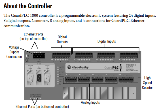
The document follows the logical mainline of "security standards → hardware awareness → installation and practical operation → functional verification", covering the entire process of controller preparation to later testing. The applicable product is GuardPLC 1800 safety controller, which is a programmable electronic system (PES) with safety certification. It integrates 24 digital inputs, 8 digital outputs, 2 high-speed counters, 8 analog inputs, and 4 GuardPLC Ethernet communication interfaces. It complies with SIL 3 (IEC 61508) and PLe (ISO 13849-1 Cat.4) safety levels and is suitable for scenarios with extremely high requirements for fault tolerance and risk control, such as mechanical safety control and process safety monitoring.
Core content sorting
(1) Controller Overview and Safety Standards
Core functions and hardware composition
Function integration: Supports the separation of secure and non secure communication. Secure communication is connected to distributed I/O, other GuardPLC controllers, or OPC servers through 4-channel 10/100BaseT RJ45 interfaces (GuardPLC Ethernet protocol); Non secure communication is achieved through 3-channel 9-pin D-shell interfaces (RS-485, etc.) to realize functions such as Modbus slave and Profibus DP slave (only 1753-L32BBBP-8A).
Hardware structure: including DIN rail installation buckle, 24V DC power interface, I/O plug-in terminal, high-speed counter interface, Ethernet interface (top 2+bottom 2), reset button (received design, anti misoperation), status indicator lights (24V DC, RUN, ERROR, PROMess, etc.). The controller is of open design and needs to be installed in a closed enclosure (protection level ≥ IP20).
Safety and Environmental Regulations
Operation qualification: It must be operated by trained professionals who are familiar with the application requirements of safety related PES (such as EN ISO 13849-1, IEC 61508).
Static electricity protection: The controller is sensitive to static electricity. When operating, it is necessary to touch a grounded object to discharge and wear a grounding wristband. It is forbidden to touch the pins or components of the circuit board. When idle, it should be stored in anti-static packaging.
Environmental requirements:
Working temperature: 0 ° C~60 ° C (32 ° F~140 ° F), storage temperature: -40 ° C~85 ° C (-40 ° F~185 ° F);
Relative humidity of 10%~95% (no condensation), pollution level 2 industrial environment, altitude ≤ 2000 meters (no need to downgrade);
It needs to be installed inside a metal casing with flame retardant properties (flame propagation level 5VA/V0, etc.), and the interior can only be accessed through tools to avoid the risk of electric shock.
(2) Installation process: from fixing to grounding
DIN rail installation (only supports DIN rail, not panel installation)
Align the guide rail: Hang the top slot of the controller on the IEC standard DIN rail (such as 199-DR1), and it is recommended to use galvanized yellow chromium steel material for the guide rail (to ensure good grounding). Fix it every 200mm (7.8 inches) and install end anchors.
Locking device: Insert a flathead screwdriver into the gap between the housing and the buckle, pull the buckle downwards, push the controller towards the guide rail, and release the buckle to complete the locking process; Reverse the operation during disassembly.
Heat dissipation requirements: Install horizontally with a minimum gap of 100mm (3.94 inches) above and below, avoiding installation above heating equipment to ensure air circulation. Install a fan if necessary.
Grounding configuration
Double grounding: The controller is functionally grounded through DIN rail, and protective grounding must be connected through a dedicated grounding screw (with grounding symbol) in the upper left corner of the housing. The grounding wire must comply with local electrical regulations (refer to Industrial Automation Wiring and Grounding Guidelines 1770-4.1).
Guide rail requirements: It is prohibited to use guide rails made of aluminum, plastic, or other materials that are prone to corrosion or have poor conductivity, in order to avoid equipment failure or safety risks caused by poor grounding.
(3) Wiring Specification: Power Supply and I/O Circuit
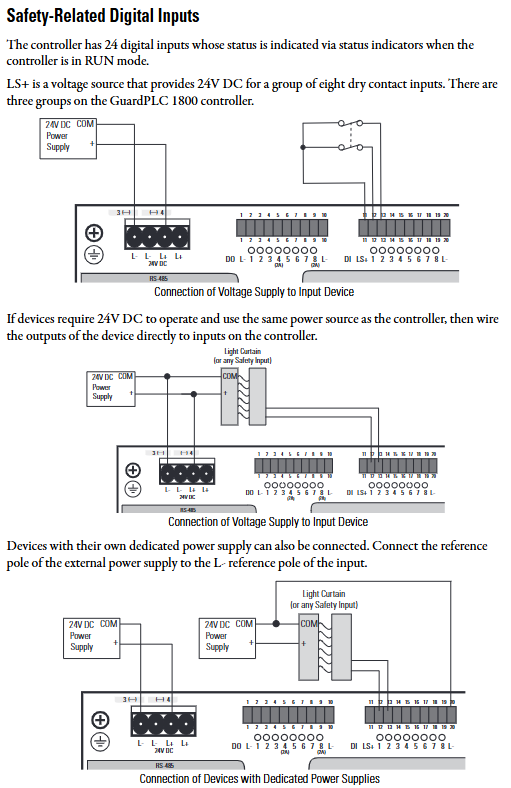
Power wiring (24V DC)
Power requirements: An isolated power supply that complies with EN 60950/UL 1950 must be used, and it must be of the SELV (Safety Extra Low Voltage) or PELV (Protection Extra Low Voltage) level. The SELV voltage should be ≤ 30V rms/42.4V peak/60V DC, and the PELV must be connected to a protective grounding.
Wiring details: Connect the power supply through a 4-pin terminal, and ensure that L+(positive pole) and L - (negative pole) are correctly connected (without reverse polarity protection, as reversing the connection may damage the controller); The terminal supports a maximum of 2.5mm ² (14 AWG) wire and requires external 10A delay fuse protection; The L+and L - terminals are internally connected, and 24V DC Daisy chain power can be supplied to other devices through the remaining terminals.
- OMRON
- ABB
- General Electric
- EMERSON
- Honeywell
- HIMA
- ALSTOM
- Rolls-Royce
- MOTOROLA
- Rockwell
- Siemens
- Woodward
- YOKOGAWA
- FOXBORO
- KOLLMORGEN
- MOOG
- KB
- YAMAHA
- BENDER
- TEKTRONIX
- Westinghouse
- AMAT
- AB
- XYCOM
- Yaskawa
- B&R
- Schneider
- KONGSBERG
- NI
- WATLOW
- ProSoft
- SEW
- ADVANCED
- Reliance
- TRICONEX
- METSO
- MAN
- Advantest
- STUDER
- DANAHER MOTION
- Bently
- Galil
- EATON
- MOLEX
- DEIF
- B&W
- ZYGO
- Aerotech
- DANFOSS
- Beijer
- Moxa
- Rexroth
- Johnson
- WAGO
- TOSHIBA
- BMCM
- SMC
- HITACHI
- HIRSCHMANN
- Application field
- XP POWER
- CTI
- TRICON
- STOBER
- Thinklogical
- Horner Automation
- Meggitt
- Fanuc
- Baldor
- SHINKAWA
- Other Brands
- UniOP
- KUKA
- Iba
- Beckhoff
-
 Basler D90 96801 100 PCB Card
 -
 Basler XR2002F Voltage Regulator (110 VAC, 48-480 Hz)
 -
 Basler SR8A-2B14B3A Regulator
 -
 Basler 9561500100 Module
 -
 Basler DECS-400 BE1-11 System
 -
 Basler DECS-100-B15 Excitation Control
 -
 Basler SCP 210 Frequency Controller
 -
 Basler SR4A-2B15B3A Static Voltage Regulator
 -
 Basler BE1-32R Power Relay
 -
 Basler PIA2400-17GM Power Interface Adapter
 -
 Basler MVC 232 Manual Voltage Control Module
 -
 Basler SSR 32-12 Static Voltage Regulator
 -
 Basler 5MW AVR Generator Voltage Regulator
 -
 Basler VR63-4B Voltage Regulator
 -
 Basler DECS-100-A05 AVR for Engine Generator
 -
 Basler DECS-100-B15 Automatic Voltage Regulator
 -
 Basler BE1-32R Directional Power Relay
 -
 Basler BE1-87B Differential Relay
 -
 Basler UFOV 260A Protective Module
 -
 Basler 9-2614-02-100 PCB Rev M
 -
Basler DECS-100-B15 Digital AVR
-
 Basler 9284900103 PS DECS-400N
 -
 Basler D4N3H1U Intertie Protection
 -
 Basler DECS-100-B15 A15 AVR
 -
 Basler KR4F Voltage Regulator
 -
 Basler BE26434 T14 Transformer
 -
 Basler SR8A-2B15B3A Regulator
 -
 Westinghouse 774B472A12 AR Relay
 -
Basler DECS-100-B15 AVR
-
Basler XR2002F Regulator 110V
-
Basler SR125-E Static Regulator
-
 Basler SSR 125-12 Regulator
 -
 Basler MOC2599 Motor Pot
 -
 Basler BE1-DFPR Feeder Relay
 -
 Basler CBS 305 Current Boost
 -
 Basler BE1-25 AutoSync
 -
 Basler MVC 300 Voltage Control
 -
 Basler BE3-25A AutoSync
 -
 Basler KR7FF Static Regulator
 -
 Basler 90-49000-100 Regulator
 -
 Basler 880 kVA Dry Type Transformer Specs
 -
 Basler Electric BE1-25 Sync-Check Relay Specs
 -
 Basler SSR 125-12 Voltage Regulator Specs
 -
 Basler Electric BE1-851 Overcurrent Relay Review
 -
Basler Electric 149D930G02 Control Sub-Assembly
-
 Basler Electric BE1-81O/UT Frequency Relay Specs
 -
 Basler Electric BE1-51/27C Overcurrent Relay
 -
 Basler Electric 149D956G02 Industrial Component
 -
Basler Electric BE1-51A Overcurrent Relay Specs
-
 Basler Electric BE1-40Q Loss of Excitation Relay
 -
 Basler DECS-200 Excitation Control System
 -
 Basler DECS-200 Voltage Regulator 56-277V AC / 125V DC
 -
Basler BE1-87T Transformer Differential Relay
-
 Basler RDP-110-S1 Protection Relay
 -
 Basler BE1-700V Digital Protective Relay
 -
 Basler BE1-951 Overcurrent Protection System
 -
 Basler DECS-300 Digital Excitation Control
 -
 Basler DECS-200 Digital Excitation Control
 -
 Basler DECS-200-1C Excitation Control System
 -
Basler DECS-200-1L Digital Excitation Control
-
 Basler Electric BE1-GPS Generator Protection System
 -
Basler Electric DECS-200-1C Digital Excitation Controller
-
 Basler Electric DECS125-15 Excitation Control with Power Module
 -
 Basler Electric BE1-87G Differential Relay
 -
 Basler Electric BE1-11 Protection System I5A3M2P2N0EA00
 -
Basler Electric DECS-200-1C Excitation Control System
-
Basler Electric BE1-11g Generator Protection Relay
-
Basler Electric DECS 125-15-B2C1 V2.0.9 Excitation Control
-
 Basler Electric BE1-81O/UT3ED1JA7N2F Frequency Relay
 -
Basler Electric BE1-81O/UT3EE1YB7N1F Frequency Relay
-
 Basler Electric DECS-200-1L Digital Excitation Control System
 -
Basler DECS125-15-B2C1 Excitation Control
-
 Basler 9507900205 SSR Retrofit Voltage Regulator
 -
 Basler BE2000E Digital Voltage Regulator
 -
 Basler BE1-GPS Generator Protection System
 -
Basler DECS-250-CN1CN1N Digital Excitation Control
-
 Basler DGC-2020 Genset Controller
 -
 Basler BE1-81O UT3ED1LA7N0F Frequency Relay (Variant)
 -
 Basler BE1-81O UT3EE1YA9S0F Frequency Relay (Variant)
 -
Basler BE1-81O Over/Under Frequency Relay
-
Basler DECS125-15 Digital Excitation Control
-
Basler Electric BE1-951 Overcurrent Protection System
-
 Basler Electric BE1-700V Digital Protective Relay
 -
 Basler Electric APR63-5 Automatic Voltage Regulator
 -
Basler Electric BE1-851 Overcurrent Protection System
-
Basler Electric DECS-250-LN1SN1N Excitation Control
-
 Basler Electric BE1-87T Transformer Differential Relay
 -
Basler Electric DECS-200-1L Excitation Control System
-
 Basler Electric 9310300100 DECS-300 Excitation Control
 -
 Basler Electric SSE-N 125-4.5KW Shunt Exciter Regulator
 -
 Basler Electric DGC-2020HD-5NS1DNSBA Genset Controller
 -
Basler Electric BE1-81-O/UT3EE1JB7N1F Frequency Relay
-
Basler Electric BE1-81T1EE1WA0N1F Frequency Relay
-
 Basler Electric BE1-25M1EA6PN5R1F Sync-Check Relay
 -
 Basler Electric BE1-GPS Generator Protection System
 -
Basler Electric DECS-250-LN1SN1N Excitation Control Rev V
-
 Basler Electric DECS-250-CN2CN1N Excitation Control
 -
Basler Electric BE1-50/51B-207 Overcurrent Relay
-
Basler Electric DECS-300-C0N0 Excitation Control System
-
Basler Electric DECS-200 Digital Excitation Control System
-
Basler Electric DECS-250-LN1CN1N Excitation Unit
-
Basler Electric DECS-250 LN2SA1D Excitation Unit Specs
-
Basler Electric BE1-87T Transformer Relay Review
-
Basler Electric BE1-11 Protection System
-
Basler Electric BE1-GPS100-E4N1H1N Protection System
-
 Allen-Bradley 442G-MABH-R Safety Module
 -
 Beckhoff CX1030-0111 PLC Assembly Profile
 -
 FANUC IC693CPU364 PLC Module
 -
 Orange Denmark Type 200816 220 PLC Specs
 -
 OMRON C200H-SNT31 Sysmac PLC Module
 -
 Allen Bradley 20AB022A3AYNANC0 PowerFlex 70
 -
 OMRON C200HW-PCU01 Position Control Unit
 -
 ABB AO845A-eA Analog Output Module
 -
 OMRON CJ1M-CPU22 CPU Unit
 -
 Allen Bradley 100-E265ED11 Contactor
 -
 Honeywell 51304511-100 Interface Module
 -
 SOLEXY BXF3S0101N0018 Gateway Module
 -
 OMRON CJ2H-CPU65 CPU Unit
 -
 Automation Direct GS2-45P0 AC Drive
 -
 M68-2000 2-Axis Motion CNC Controller
 -
 OMRON CJ1M-CPU11 V3.0 PLC CPU Unit
 -
 OMRON CJ1W-NC413 4-Axis Positioning Controller
 -
 OMRON 3G2A3-PRO16 Programming Console HMI
 -
 Siemens 3VT8440-2AA04-2GA2 Molded Case Circuit Breaker
 -
 Siemens 3RT5045 Contactor Series
 -
 OMRON C200HS-CPU01-E SYSMAC PLC Controller
 -
 OMRON C500-NC103-E Positioning Control Unit
 -
 OMRON CJ1W-TC001 Temperature Control Unit


