
SIEMENS SIMATIC HMI Basic Panels Operating Manual
Today, visualization is part of the standard repertoire for most machines. The cost factor plays a crucial role in this case, especially for small machines and simple applications. HMI devices with basic functions are often fully sufficient for simple applications.
This is exactly the demand that we intend to meet – with our new SIMATIC HMI Basic Panels. By concentrating on the essentials, the Basic Panels offer exactly those basic features that are demanded – at the right price. A perfect cost-to-performance ratio.
Like all devices in our product catalog, the new Basic Panels offer proven SIMATIC quality and – regardless of their display dimensions – many software functions as standard: for example, an alarm system, recipe management, trend functionality and language switching.
Users therefore profit from the advantages of visualization, such as improved process quality, even with simple applications.
1. Preparation before connection
Tools and accessories: Prepare a No. 2 Phillips screwdriver, a No. 3 Phillips screwdriver, a TX20 Phillips screwdriver, a crimping tool, power terminals, and a 24VDC power supply (current must meet equipment specifications, refer to the "Power supply" section).
Connection sequence: Strictly follow the order of "equipotential connection → power connection → configuration PC connection → PLC connection", do not reverse, and provide sufficient strain relief for all cables to avoid contact breakage or wire detachment.
2. Equipotential connection
Connection necessity: There may be potential differences between equipment components separated by space. If the shielding layer of the data cable is grounded at both ends and connected to different equipment components, it may generate large balanced currents and damage the interface; Systems powered by different power sources may also generate potential differences, and the risk needs to be reduced through equipotential connections.
Connection requirements:
Conductor requirements: The equipotential bonding conductor should be made of copper or galvanized steel, with a cross-sectional area of not less than 16mm ² (to ensure maximum balanced current), and should establish a large surface area contact with the grounding/protective conductor to prevent corrosion.
Shielding treatment: The shielding layer of the data cable needs to be clamped flat and clamped onto the equipotential rail near the HMI device using a suitable cable clamp.
Wiring requirements: The equipotential bonding conductor and data cable should be laid in parallel with minimal gap.
Prohibited items: The cable shielding layer shall not be used for equipotential connection. MPI and PROFIBUS DP networks must use cables with sufficient cross-section, otherwise it may damage the interface module.
Operation steps:
Connect the functional grounding of the HMI device with a grounding wire with a cross-sectional area of 4mm ².
Connect the grounding wire to the equipotential rail.
3. Power connection
Cable requirement: Use power cables with a maximum cross-sectional area of 1.5mm ².
Cable handling:
Strip the ends of the two power cables by 6mm.
Install cable conduit at the exposed end of the cable.
Secure the cable conduit at the end of the cable using crimping pliers.
Connection steps:
Insert two power cables into the power terminals using a Phillips screwdriver and secure them in place.
Connect the HMI device to the power terminal and ensure correct polarity (distinguish between+24VDC and GND).
Turn off the power supply.
Insert the remaining two cable ends into the power terminal and secure them, then confirm the polarity again.
Safety warning: Only 24VDC power supply can be used, and the power supply current must comply with the equipment specifications (refer to the "Specifications" section). Incorrect specifications of power supply may cause equipment damage.
4. Programming equipment and configuration PC connection
Programming Device Connection (Basic Panel DP):
Function: Can be used for project transfer and device image transfer, but cannot be used to restore factory settings.
Step: Turn off the HMI device, confirm that the DIP switch on the back of the device is in the designated position, and connect the RS485 PROFIBUS connector to the device.
Configure PC connection:
Function: Supports project transfer, device image transfer, and factory reset.
Basic Panel DP Connection: Use PC/PPI cable or USB/PPI cable for connection, and configure the DIP switch of the cable to set the transmission rate (such as 115.2kbps corresponding to DIP1=1, DIP2=1, DIP3=0). If the connection is lost during operating system updates, the bit rate needs to be reduced; When using high bit rates, PC/PPI cable version 3 or above is required (version number printed on the cable, such as "E stand 3").
Basic Panel PN Connection: Use the "IE FC RJ45 Plug 2x2" RJ45 plug (order number 6GK1901-1BB10-2AA0) and connect it with a standard CAT-5 Ethernet cable; Attention should be paid to Ethernet data network security, and users need to ensure network security themselves to avoid risks such as device overload.
5. PLC connection
Connection prerequisite: The HMI device must have an installed operating system and executable projects.
Connection specification: When wiring, the data line should be parallel to the equipotential connecting conductor, and the shielding layer of the data line should be grounded.
Basic Panel DP Connection:
Direct connection: Connect SIMATIC S7-200, S7-300/400, S7-1200 through RS422/RS485 interface.
Converter connection: Connect third-party PLCs such as Modicon Modbus and Allen Bradley DF1 through the converter in the accessory (such as RS422 to RS232).
Interface configuration: There is a DIP switch on the back of the device for RS422/RS485 interface configuration. The factory default setting is to communicate with SIMATIC PLC through RS485, which needs to be adjusted according to the DIP switch setting diagram on the back of the device (such as RTS signal position).
Basic Panel PN Connection:
Connecting devices: Connect SIMATIC S7-200, S7-300/400, and S7-1200 with PROFINET interface via PROFINET/LAN.
- OMRON
- ABB
- General Electric
- EMERSON
- Honeywell
- HIMA
- ALSTOM
- Rolls-Royce
- MOTOROLA
- Rockwell
- Siemens
- Woodward
- YOKOGAWA
- FOXBORO
- KOLLMORGEN
- MOOG
- KB
- YAMAHA
- BENDER
- TEKTRONIX
- Westinghouse
- AMAT
- AB
- XYCOM
- Yaskawa
- B&R
- Schneider
- KONGSBERG
- NI
- WATLOW
- ProSoft
- SEW
- ADVANCED
- Reliance
- TRICONEX
- METSO
- MAN
- Advantest
- STUDER
- DANAHER MOTION
- Bently
- Galil
- EATON
- MOLEX
- DEIF
- B&W
- ZYGO
- Aerotech
- DANFOSS
- Beijer
- Moxa
- Rexroth
- Johnson
- WAGO
- TOSHIBA
- BMCM
- SMC
- HITACHI
- HIRSCHMANN
- Application field
- XP POWER
- CTI
- TRICON
- STOBER
- Thinklogical
- Horner Automation
- Meggitt
- Fanuc
- Baldor
- SHINKAWA
- Other Brands
- UniOP
- KUKA
- Iba
-
 Guardmaster 440R-D22R2 Safety Relay Specifications
 -
 NL12880BC20-10ND Industrial Display Panel Data
 -
 LFI 12X5326-S1 Slide-in Control Board Technical Data
 -
 Modicon AS-9370-001 Programmable Controller Data
 -
 Mitsubishi Kakoki E-01B-4130 PLC Module Overview
 -
 Guardmaster 440R-D22S2 Dual Input Safety Relay Data
 -
 NL10276AC30-48D Industrial LCD Display Panel Data
 -
 GE ICMFA000000-ABAC Field Control Module Specification
 -
 Siemens 6SN1123-1AB00-0BA1 SIMODRIVE Module Review
 -
 Siemens 6SL3210-1SE23-2AA0 Power Module Technical Data
 -
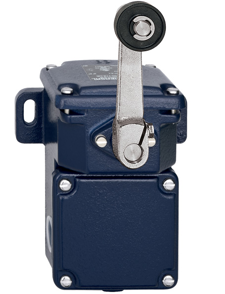 Schmersal T.250-11z-t Limit Switch
 -
 Schmersal T.250-11z-t Limit Switch
 -
 Honeywell 900H32-0102 ControlEdge 900 PLC
 -
 Siemens 6FX1132-1BA01 PCB B84141-A-A40
 -
 BEMAC UST-202-D 1307D PLC Circuit Board
 -
 Mitsubishi HS-MF23-S2A Servo Motor
 -
 B&R 3AI775.6 Analog Input Module
 -
 Omnipure 69003 Rev 11 3-Phase Gate Board PCB
 -
 Pilz 751134 PNOZ s4 C Safety Relay
 -
 Proface PFXGM4301TAD HMI Graphic Panel
 -
 Keyence KV-RC8BXR Programmable Controller
 -
 Siemens 6GK7243-1BX30-0XE0 CP 1243-1 Ethernet Module
 -
 Mitsubishi GT2310-VTBA GT2310-VTBD HMI 10.4 Inch
 -
 Schmersal SRB-NA-R-C.21-24V Safety Relay Module
 -
 Emotron 01-2520-40 M20 Shaft Power Monitor 3x380-500V
 -
 Omron CQM1 SYSMAC PLC System PA203 ID211 OC221
 -
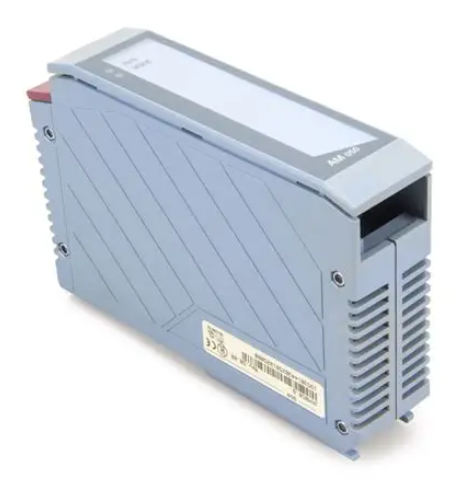
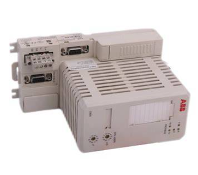 ABB CI830 3BSE013252R1 Profibus DP V1 Module
 -
 B&R 4PP035.0300-01 Power Panel PLC Module
 -
 SICK S30A-6111CL S3000 PROFINET Safety Laser Scanner
 -
 Siemens 6ES7215-1HG40-0XB0 CPU 1215C AC/DC/RLY
 -
 Automation Direct H2-ECOM100 Ethernet Module Details
 -
 Siemens 6GK1143-0TB01 CP 1430 TF Module Review
 -
 Siemens Simatic 505 10 Slot PLC Rack Technical Review
 -
 Automation Direct EZ-SP Message Display Unit
 -
 Mitsubishi A1SJ71QE71N-B5T Ethernet Interface Unit
 -
 Modicon AS-P810-000 Modbus Plus Processor Unit
 -
 Honeywell 51309241-175 TK-PPD011 PWA Specifications
 -
 Omron S8AS-24006N Smart Power Supply Specifications
 -
 Beckhoff EL3218-0018 EtherCAT Terminal Specifications
 -
 Omron CJ1W-PRT21 PROFIBUS-DP Interface Unit
 -
 Inovance AC810-0122-U0R0 PLC Controller
 -
 Cypress CY7C1021CV33-10ZXCT 1Mb SRAM IC
 -
 GE Fanuc IC695CPU315-CD PLC CPU Module RX3i
 -
 Drager 8312088 PCB Safety Module PAC 5500
 -
 Weltronic H70-T02A S430-V1.2 Weld Timer PLC
 -
 B&R 3AM051.6 PLC Analog Input Module
 -
 Schneider BMENOC0301 Communication Module M580
 -
 Mitsubishi FX3UC-32MT-LT PLC Controller
 -
 Omron TZ-1G TZ-1GV TZ-1GV2 TZ-1GV22 Motion Switch
 -
 Mitsubishi AJ71C21-B1-S2 PLC Controller 424749
 -
 Beckhoff EL5042 EtherCAT Encoder Terminal BiSS C
 -
 Eaton easyE4 Programmable Relay 12 Inputs 8 Outputs
 -
 Carel PCO5 P+ 500BAA000L0 Programmable Controller
 -
 Siemens 6ES7223-1PL22-0XA0 EM223 I/O Module 16DI 16DO
 -
 Lenze EMF2179IB DeviceNet Communication Module
 -
 Mitsubishi Q173DCPU Motion CPU Module
 -
 B&R X20AT2222 Temperature Input Module Pt100
 -
 Siemens SITOP UPS1100 Battery Module 7Ah 6EP4134-0GB00-0AY0
 -
 Mitsubishi QJ71DN91 DeviceNet Master Slave Module
 -
B&R X20AO4622 Analog Output Module 4 Channels
-
 B&R X20CP1486 Controller Manual
 -
 Siemens 6ES7134-4GB51-0AB0 Module Manual
 -
 Schneider LMC201CAA10000 Controller Manual
 -
 Fuji Electric NP1L-RS4 Module Guide
 -
 Mitsubishi FX2N-16LNK-M Master Guide
 -
 Yaskawa SGDM-08ADA SGMAH-08AAA41 Manual
 -
 Fanuc A20B-0008-0470 Board Manual
 -
 Calpeda T 70/B Module Specifications
 -
 Eurotherm TC3000 Power Drive Specifications
 -
 Mitsubishi QJ71GP21S-SX Module Manual
 -
 B&R X20AI4622 Analog Input Module 4 Channels
 -
 Siemens Simatic S5 PLC I/O and CPU Modules
 -
 Tel 38950 PCB Board 5044-000171-11 AP9Z-2033A
 -
 Sanyo PLC-XTC50L Multimedia Projector
 -
 Siemens 6GK7243-5DX30-0XE0 CP 243-5 AS-Interface
 -
 Omron V680-CA5D02-V2 RFID Controller
 -
 Pilz 570640 PSEN SL-1.0P Safety Switch
 -
 Schneider LXM62DD27D21000 Servo Drive
 -
 Pilz 401112 PITswitch en1.1a-5m-s Emergency Stop Switch
 -
 Pilz 774350 P2HZ X3 Safety Relay
 -
 Siemens S30810-Q1113-X4-6/02 EWSD Module Board
 -
 Honeywell 30751044-008 ROM PLC Control Board
 -
 Allen-Bradley 440R-W23219 MSR310P Safety Relay
 -
 Siemens 6GK5204-2BB10-2AA3 Industrial Ethernet Switch
 -
 Siemens YSU C32353ADDAGS C98043 PC Board
 -
 Schneider TM241CEC24T PLC Controller Modicon M241
 -
 VARIAN E15000591 PLC PCB Assembly 132102
 -
 Schneider Electric HMIG3U PLC Controller Module
 -
 Siemens 6ES7148-4FC00-0AB0 ET200 IO Module
 -
 Siemens A5E30484420 Simatic IPC Redundant PSU
 -
 Allen Bradley 1771-A3B Chassis Manual
 -
 Schneider BMEH586040 Processor Manual
 -
 Mitsubishi GT2508 Graphic Panel Manual
 -
 Mitsubishi FX2N-16LNK-M Link Module Manual
 -
 Beckhoff EL3011 Analog Terminal Manual
 -
 Siemens 6SN1145-1AA01-0AA1 Infeed Manual
 -
 Proface SP5000 Series Display Specifications
 -
 NUM 0204203001 Axes Board Manual
 -
 Square D LV434001 Ethernet Interface Manual
 -
 Omron NA5 Series HMI Module Specifications
 -
 ABB 57619104E Inverter PCB Control Board
 -
 Allen-Bradley 100-E205ED11 MCS-E Contactor 205A
 -
 Omron NS12-TS01-ECV2 Series Operation Panel
 -
 Allen-Bradley 440R-EM4R2 Guardmaster Safety Relay
 -
 Omron CS1D-DPL01 Duplex System PLC Module
 -
 Beckhoff CX2030-0115 Embedded PC Controller
 -
 ABB Pluto S20 v2 Cfs Safety PLC 2TLA020070R4700
 -
 B&R X20AT4222 Analog Input Module RTD
 -
 Inovance H3U-3624MT PLC Controller
 -
 GE Fanuc IC698CPE010 PLC CPU Module
 -
 Texas Instruments Siemens 505-6208-A Analog Input Module
 -
 VDISP 0035416 Card Module Industrial Display Controller
 -
 HITACHI TX09D80VM3CCA 3.5 Inch LCD Screen 240x320
 -
 Siemens 545 555 1105 1106 PLC Controller
 -
 H2-ECOM100 PLC Communication Module Ethernet
 -
 B&R X20CS1012 PLC Module X20 CS 1012
 -
 Siemens 6ES7212-1HF40-0XB0 PLC Module 24VDC
 -
 Omron C120-0C222 IO Module 3G2A6-0C222
 -
 Electromatic Denmark PLC TYPE 200816 Industrial Controller
 -
 SANYO PLC-XTC50L Projector 50-60Hz LCD Installation
 -
 LTi SO84.450 Servo Drive Controller - 450A Three-Phase BG7
 -
 LTi SO84.375 Servo Drive Controller - 375A Three-Phase BG7
 -
 LTi SO84.325 Servo Drive Controller - 325A Three-Phase BG7
 -
 LTi SO84.250 Servo Drive Controller - 250A Three-Phase BG7
 -
 LTi SO84.170 Servo Drive Controller - 170A Three-Phase BG6a
 -
 LTi SO84.143 Servo Drive Controller - 143A Three-Phase BG6a
 -
 LTi SO84.110 Servo Drive Controller - 110A Three-Phase BG6
 -
 LTi SO84.090 Servo Drive Controller - 90A Three-Phase BG6


