
Honeywell X-DCS3000 Digital Integrated System Manager
Honeywell X-DCS3000 Digital Integrated System Manager
Introduction: Challenges of Modern Public Broadcasting System and the Positioning of X-DCS3000
In complex environments such as airports, rail transit, large commercial complexes, and industrial plants, public address systems not only meet the needs of daily background music and broadcast notifications, but also undertake the task of guiding personnel evacuation in emergency situations such as fires. Traditional broadcasting systems have obvious shortcomings in audio source management, partition control, amplifier redundancy, fault detection, etc., especially when the main power supply is cut off or the amplifier channel fails, the reliability of the system is severely tested.
The Honeywell X-DCS3000 Digital Integrated System Manager (DCS), as the core unit of the X-618 public address system, provides a cost-effective and reliable solution for complex application scenarios through a highly integrated audio matrix architecture, dual power backup mechanism, 8+2 channel amplifier redundancy design, and networked scalability.
This article will provide a comprehensive technical analysis of X-DCS3000 from the aspects of system architecture, core functions, interface configuration, security mechanisms, common troubleshooting, and engineering deployment recommendations.
System Overview and Core Architecture
2.1 Equipment positioning and basic functions
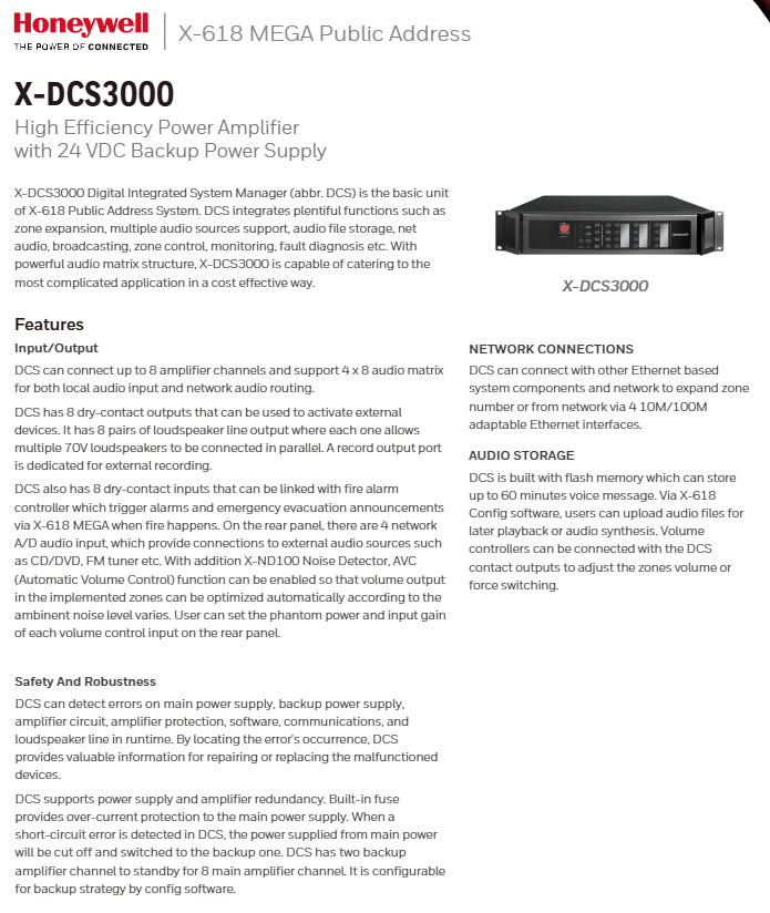
The X-DCS3000 is a 1U rack mounted device (482 × 88 × 420 mm) with a net weight of 9.3 kg. As the "brain" of the X-618 system, it integrates the following functions:
Partition extension
Multi channel audio source support
Local storage of audio files
Network audio transmission
Broadcast scheduling and partition control
Real time monitoring and fault diagnosis
Its built-in audio matrix structure supports up to 8 amplifier channels and allows for 4 × 8 channel audio matrix switching, covering both local audio input and network audio routing.
2.2 Power backup and redundancy design
One of the most prominent safety features of X-DCS3000 is its dual power input:
Main power supply: AC 100-240V, 50/60Hz, built-in T2AL 250V fuse, providing overcurrent protection.
Backup power supply: DC 21.5V -28.5V (typical 24V), can be supplied by an external battery or DC power source.
When the main power supply experiences a short circuit fault or power outage, the system automatically switches to the backup DC power supply to ensure uninterrupted broadcasting. In addition, the device also provides a DC 24V/1A output, which can be used to power external auxiliary devices such as noise detectors.
2.3 Power amplifier redundancy strategy
The system supports 8 primary power amplifier channels and 2 backup power amplifier channels. By configuring the software, users can customize backup strategies:
1: 1 Backup: Each backup channel takes over a fixed main channel.
N: 1 Backup: Two backup channels can take over any faulty main channel.
When any main power amplifier malfunctions (such as overheating, overload, output short circuit), DCS automatically detects and routes the signal to the backup power amplifier, while outputting a fault alarm through dry contacts.
Detailed explanation of input and output interfaces and engineering wiring
3.1 Audio Input Interface
The device provides multiple audio input methods:
Interface type, quantity, technical parameters, purpose
Auxiliary input AUX1 10 dBV (1V), 10k Ω CD/DVD, mixing console and other line levels
Auxiliary input AUX2/3 2-40 dBV~0 dBV, 10k Ω microphone or low-level signal, supports phantom power supply
Network A/D audio input 4 10/100M Ethernet from X-618 network components or external IP audio source
DCL input has 8 channels, with up to 5 modules per channel that can be connected to noise detectors and EOL terminal modules for automatic volume control (AVC) and line end monitoring
Engineering Tip: The AUX2/3 input can be separately set for gain and phantom power (+48V), suitable for condenser microphones. If you need to connect a long-distance microphone, it is recommended to use shielded twisted pair cables and avoid sharing them with strong electrical cables.
3.2 Audio output interface
Speaker circuit output: 8 channels, each with 70V constant voltage output, maximum load power of 250W/channel. Support line fault detection (short circuit, open circuit).
Auxiliary output: 2 channels, 1.2V (<1.6 dBV), used to connect additional amplifiers or area extenders.
Recording output: 1 channel, 0 dBV, constant level, compatible with external recording devices.
3.3 Control and Status Interface
Dry contact input: 8 channels, can be connected to the relay output of the fire alarm controller (FACP). When any input is activated, DCS triggers emergency evacuation voice according to the preset priority.
Dry contact output: 8 channels, each providing NO, NC, COM contacts, with a maximum switching capacity of 250V AC/30V DC, 2.5A. Can be used to control external indicator lights, access control release devices, backup amplifier startup, etc.
RS-485 port: Connect to X-618 configuration software or remote control panel (such as X-NPMS).
Ethernet interface: 4 10/100M adaptive ports, supporting switch cascade or ring network connection, convenient for expanding partitions.
Deep analysis of core functions
4.1 Audio Storage and Timed Broadcasting
DCS is equipped with 1GB of flash memory (606MB of which is used to store audio files), which can store up to 60 minutes of voice messages (WAV format). Users upload audio files through X-618 Config software for:
Automatically play on a scheduled basis (such as end of work ringtones and midday music)
Emergency evacuation voice synthesis (such as "Attention, there is a fire alarm now, please evacuate from the nearest exit")
Multilingual information carousel
Combined with X-SMART scheduling software, it can achieve weekly/daily scheduled broadcasting plans, supporting up to 255 priority levels, suitable for multi-level broadcasting needs of large venues.
4.2 Network Audio and Partition Expansion
Through 4 Ethernet interfaces, X-DCS3000 can:
Connect other X-DCS3000 units and expand the system to a maximum of 256 broadcast partitions.
Receive real-time calls from the X-NPMS network paging microphone.
Integrate into the building automation network and trigger designated broadcasts through third-party systems such as BMS.
Network audio routing capability: The system can simultaneously play 4 different audio streams (such as background music in Zone A, fire evacuation in Zone B, manual notifications in Zone C, and timed announcements in Zone D), with each zone independently selecting the audio source.
4.3 Automatic Volume Control (AVC)
When connecting the X-ND100 noise detector to the DCL input channel, the AVC function is automatically enabled. The detector monitors the environmental noise level in real-time (such as airport waiting halls and workshops), and the DCS dynamically adjusts the output volume of the corresponding broadcast zone based on the preset noise compensation curve. For example:
Environmental noise 65 dB → output+0 dB
Environmental noise 80 dB → output+6 dB
Environmental noise 90 dB → output+10 dB
This ensures that the broadcast information is always audible without causing disturbance to the public during quiet hours.
4.4 Fault self diagnosis and status indication
During the operation of X-DCS3000, the following items are continuously monitored, and any abnormalities are immediately alerted through panel indicator lights, dry contact outputs, network messages, and other means:
Main power supply voltage and fuse status
Backup power supply voltage
Temperature, overcurrent, short circuit, and DC offset of each amplifier channel
Power amplifier protection status (overheating, overvoltage)
Software watchdog and communication link
Open/short circuit of 8-channel speaker circuit
Fault information can be located in specific channels, greatly reducing maintenance and troubleshooting time. For example, the "Zone Status" indicator light on the panel will display whether the corresponding speaker circuit is normal, with red indicating a fault.
Front panel operation and status interpretation
5.1 Region selection button
The 8 area selection buttons correspond to 8 speaker output channels. It can be selected individually or in bulk for broadcasting or muting.
5.2 Sound source selection and emergency mode
Audio source selection button: Select the audio source (AUX 1~3, network audio, built-in voice, etc.) currently used for broadcasting.
Emergency mode button: One click trigger for emergency evacuation of the entire area, with the highest priority, ignoring any current broadcasts.
5.3 Status indicator lights
Meaning of indicator lights
The main power supply of the Power device is normal
Backup DC power supply in progress
Fault system detects faults (amplifier, circuit, power supply, etc.)
Disabled: The corresponding channel has been disabled by software
Running is broadcasting
Delay broadcast delay start (priority waiting)
5.4 Special operation keys
Select All: Quickly operate on all regions.
Reset: Clear the fault latch status (the fault needs to be resolved first).
Error Confirm: Mute the fault buzzer and confirm the alarm.
Typical Engineering Applications and Deployment Suggestions
6.1 Rail Transit Platform Broadcasting System
Requirement: The platform area requires three levels of broadcasting: background music, train arrival announcement, and emergency evacuation announcement. Require that the main power supply can still operate for at least 30 minutes when it fails, and that a single amplifier failure does not affect the overall performance.
Solution:
Using X-DCS3000 as the main controller, connect 4 250W main power amplifiers to drive 8 station zones (each amplifier pushing 2 zones).
Configure two 250W backup power amplifiers using an N: 1 redundancy strategy.
The main power supply is taken from the station power supply, and the backup power supply is connected to a 48V battery pack (reduced to 24V).
Connect the dry contacts of the fire alarm system, and when the fire alarm signal is triggered, automatically play pre recorded evacuation voice and forcefully cut off all background music.
6.2 Large Factory Workshops
Requirement: In high noise environments (85-95 dBA), automatic volume compensation is required. At the same time, timed ringing and machine maintenance team paging are required.
Solution:
Install X-ND100 noise detectors in each workshop and connect them to DCL input.
Configure AVC curve: For every 5 dB increase in noise, the output increases by 3 dB (upper limit+12 dB).
Set a daily ringtone schedule (for work, lunch break, and after work) through software configuration.
Connect the X-NPMS paging microphone, and the machine maintenance team leader can make targeted calls to the designated workshop.
6.3 Hotel Conference Center
Requirement: Multiple conference rooms should play different audio sources independently, while the background music in the lobby should not be interrupted. Need to support remote volume control.
Solution:
Using 4 Ethernet interfaces, connect multiple regional expansion units to achieve 32 partitions.
Each conference room is equipped with a wall mounted volume controller (which controls the attenuator through dry contact output).
Connect the recording output port to a digital recorder to record all conference broadcasts.
Common troubleshooting and engineering maintenance
7.1 Device cannot start, Power light does not light up
Possible reasons:
The main power fuse is blown
The main power supply is not connected or the voltage is abnormal
Backup power supply connected but voltage too low (<21.5V)
Solution steps:
Check if the AC input socket has 220V.
Open the fuse holder, check if the T2AL 250V fuse is blown, and replace it with a fuse of the same specification if necessary.
Measure the backup power terminal voltage, which should be between 21.5-28.5V.
If the main power supply still does not start after recovery, try using only the backup power supply to troubleshoot the main power module.
7.2 Fault reported on a certain speaker circuit
Performance: The corresponding area indicator light turns red, and the system generates a fault contact output.
Troubleshooting:
Disconnect the output terminal of the speaker and measure the resistance of the circuit with a multimeter.
The DC resistance of a normal 70V constant voltage circuit (with multiple speakers connected in parallel) is usually several ohms to tens of ohms.
If the resistance is 0 Ω → short circuit in the circuit; If it is infinite, the circuit will break.
Check if the transformer and volume switch on the circuit are damaged.
After repairing, press' Error Confirm 'to clear the alarm.
7.3 Over temperature protection for a certain amplifier channel
Reason:
Load exceeding limit (connected to speakers exceeding 250W)
Poor heat dissipation of the cabinet
The ambient temperature exceeds 55 ° C
handle
Check the actual load power of the channel (the sum of the rated power of all connected speakers should not exceed 80% of the rated power of the amplifier).
Clean the ventilation filter of the cabinet to ensure sufficient space in front and behind the equipment.
Reduce the ambient temperature or increase the exhaust fan.
7.4 Intermittent network audio
Possible reasons:
Ethernet switch congestion or broadcast storm present
The network cable is too long (over 100 meters) or of poor quality
IP address conflict
solve:
Assign X-DCS3000 and network audio devices to independent VLANs and isolate the broadcast domain.
Use Cat5e or higher shielded Ethernet cables to ensure a single segment distance of ≤ 90 meters.
Log in to the configuration software and check the network packet loss rate (<0.1% is normal).
7.5 Emergency triggering does not activate evacuation voice
Troubleshooting:
When the dry contact output of the fire alarm controller is confirmed to be closed, there is a voltage change at the corresponding DCS dry contact input terminal (using a multimeter).
Check if the input port in the configuration software is associated with the correct evacuation voice file (MP3/WAV).
Confirm that the evacuation priority (usually up to 255) has not been blocked by other tasks.
Try manually pressing the Emergency button on the panel to verify if the voice playback is working properly. If it is normal, it indicates an input configuration error.
Installation and wiring safety regulations
Power wiring: The main power supply must use power cords that comply with local electrical regulations (including AC power cords). It is recommended to use copper core flexible wires with an area of 2.5mm ² or more and install a 15A fuse for backup power cords.
Speaker circuit: 70V constant voltage circuit must not be shared with low-voltage control lines (such as RS-485) to avoid inductive interference. All horn polarities must be consistent to avoid phase cancellation.
Dry contact input: When used for fire linkage, it is recommended to use shielded cables with a single ended grounding of the shielding layer to prevent accidental triggering.
Grounding: The rear panel of the equipment provides a grounding terminal, which must be reliably connected to the cabinet grounding strip, and the grounding resistance should be less than 4 Ω.
Heat dissipation: 1U space should be reserved above and below, and the side air inlet should not be blocked. The ambient temperature shall not exceed 50 ° C.
Laser/Safety: Although this device does not have a laser, there are fuses and high-voltage capacitors inside. After power failure, you need to wait for 1 minute before operating.
- ABB
- General Electric
- EMERSON
- Honeywell
- HIMA
- ALSTOM
- Rolls-Royce
- MOTOROLA
- Rockwell
- Siemens
- Woodward
- YOKOGAWA
- FOXBORO
- KOLLMORGEN
- MOOG
- KB
- YAMAHA
- BENDER
- TEKTRONIX
- Westinghouse
- AMAT
- AB
- XYCOM
- Yaskawa
- B&R
- Schneider
- Kongsberg
- NI
- WATLOW
- ProSoft
- SEW
- ADVANCED
- Reliance
- TRICONEX
- METSO
- MAN
- Advantest
- STUDER
- KONGSBERG
- DANAHER MOTION
- Bently
- Galil
- EATON
- MOLEX
- DEIF
- B&W
- ZYGO
- Aerotech
- DANFOSS
- Beijer
- Moxa
- Rexroth
- Johnson
- WAGO
- TOSHIBA
- BMCM
- SMC
- HITACHI
- HIRSCHMANN
- Application field
- XP POWER
- CTI
- TRICON
- STOBER
- Thinklogical
- Horner Automation
- Meggitt
- Fanuc
- Baldor
- SHINKAWA
- Other Brands
- UniOP
- KUKA
- Iba
-
 ABB SCC-C 23070-0-10232110 gas cooler
 -
 Sick LGTN101-521 CPU Module
 -
 Okuma 1911-2836 PLC Circuit Board
 -
 Mitsubishi Melsec PM-120M PLC
 -
 Omron F210-C15 Vision Mate Controller System
 -
 Siemens 7ML5110-1GD07-4AF3 Ultrasonic Level Gauge
 -
 ABB Pluto S46 V2 Safety Relay
 -
 Omron Z3RN-5A Optical Serial Link
 -
 Omron R7D-APA3H 30W Servo Drive
 -
 Giddings Lewis 502-03638-41R3 PLC Processor
 -
 Omron SCY-P1 Sequencer Controller
 -
 Siemens C98043-A7002-L1-13 PCB Board
 -
 SACS TECNICA Palletizer PC PLC Control System
 -
 AutomationDirect T1F-14THM PLC Module T1F14THM
 -
 OMRON C200H-AD003 Analog Input Unit PLC Module
 -
 Applied Materials 0010-A0000 Electricity Box PLC 200mm
 -
 ABB RVT-6 Power Factor Controller RVT6
 -
 Allen-Bradley 2094-BC01-MP5-M Kinetix 6000 Axis Module
 -
 OMRON FQM1S-MC233 Motion Controller PLC Module
 -
 OMRON C200H-SNT31 PLC Special I-O Module
 -
 Yaskawa SGMPH-04AAA61D-OY Servo Motor 400W 200V
 -
 Yaskawa SGMGH-09DCA6F-OY AC Servo Motor 850W 400V
 -
 REFU ELEKTRONIK SR17002 PLC Logic Module Circuit Board
 -
 Siemens 6DP1231-7AA PLC Board Module Industrial Control
 -
 ABB SACE ISOMAX S3 N 160 Molded Case Circuit Breaker
 -
 OMRON C120-SC024-V1 SYSMAC C120 Compact PLC Unit
 -
 OMRON CJ1W-SCU41-V1 Serial Communication Unit PLC Module
 -
 OMRON 3G3MX2-A4110-ZV1 MX2 Variable Frequency Drive
 -
 Yaskawa SGDH-04AE-OY Sigma-II Servo Driver 400W 200V
 -
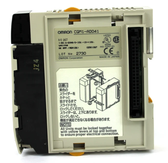 OMRON CQM1-AD041 Analog Input Module PLC I/O Unit
 -
 Delta Omega XML2-0060-45-4/S-A Servo Drive
 -
 Omron CJ1W-AD041 Analog Input
 -
 Omron CJ1W-NC271 Position Control Unit
 -
 Omron CJ1G-CPU45H PLC CPU
 -
 Omron CJ1W-EIP21 EtherNet/IP Unit
 -
 Omron F210-C15 Vision Mate Controller
 -
 Omron CQM1H-ADB21 Analog I/O Board
 -
 Omron GRT1-PRT PROFIBUS DP-V1 Adapter
 -
 Omron CP1H-Y20DT-D PLC CPU
 -
 TE.CO TFX 4G 1.5 Grey Cable 470m
 -
 Yaskawa SGDH-04AE-OY Servo Driver 400W 200V
 -
 OMRON CJ1H-CPU66H V4.0 PLC CPU
 -
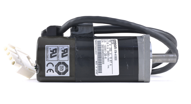 OMRON R7M-A10030-BS1 Servo Motor 200W 100V
 -
 OMRON FQM1-MMA21 Motion Controller
 -
 Yaskawa SJDE-08APA Servo Amplifier
 -
 OMRON CQM1-AD041 Analog Input Unit
 -
 Siemens OCI55 Dialogue Module Landis
 -
 OMRON F350-C10E Image Processing Unit
 -
 OMRON NT10S-SF121 HMI Terminal
 -
 SIEMENS 3RB1262-0LB31 Overload Relay
 -
 OMRON YASKAWA SGDS-02A12A Servo Drive
 -
 TE.CO TFX 4G 1.5 Grey Cable ST 500m
 -
 FANUC A16B-3200-0362 PCB Control Board
 -
OMRON CQM1-ARM21 Analog Output Unit
-
 Allen-Bradley 1788-EN2DN Ethernet DeviceNet Gateway
 -
 Siemens 3VL9440-7EE40 3VL4740-2AA46-0AA0 Circuit Breaker
 -
 OMRON CJ1W-AD041-V1 Analog Input Unit
 -
 OMRON CQM1-AD041 CQM1-IPS02 Analog Input Power Supply
 -
 Texas Instruments System 505 PLC 525-110 525-1102
 -
 OMRON CQM1-AD042 Analog Input Unit
 -
 Yaskawa SGDH-04AE-OY Servo Driver 200V 400W
 -
 CTI 2512 75W Power Supply for CTI 2500
 -
 Omron F300-B5 Image Processing Unit
 -
 Mitsubishi 15050-PR01A PLC Board
 -
 Omron CQM1-TC101 Temperature Controller
 -
 SCE M68-2000 2 Axis Motion Controller HW 2.3/B
 -
 Omron 3Z4SP-C22 Visual Positioning Sensor
 -
 Omron 3G3SV-BB007-E 0.75kW VFD
 -
 CML 6622 IRD Entek AW10528 Vibration Monitor
 -
 Omron CP1L-EL20DR-D PLC CPU
 -
 TE.CO TFX 4G 1.5 Grey Cable 500m
 -
 Mitsubishi Electric 3BK23057 Circuit Board Module
 -
 OMRON FQM1-MMP21 Motion Control Module
 -
 OMRON CP1E-E40SDR-A Micro PLC CPU Unit
 -
 KEBA CU201 PLC Control Unit
 -
 OMRON F150-C10E-2 Vision Sensor Controller
 -
 YASKAWA SGDH-04AE-OY Sigma-II Servo Driver
 -
 OMRON CS1H-CPU65-V1 PLC Central Processing Unit
 -
 OMRON NB7W-TX01B Interactive Display HMI
 -
 OMRON C500-TU002E Programmable Logic Controller Timer Unit
 -
 OMRON C200HW-PRT21 PROFIBUS DP Slave Unit
 -
 ExcelTech MX-5-S-I-6-4 Static Transfer Switch
 -
 Allen-Bradley 100-B300ND3 Contactor 304A 600V
 -
 Pasaban MTC-3052 Fast I/O PLC Card
 -
 OMRON CQM1-TC101 Temperature Control Unit
 -
 OMRON 3G3SV-BB007-E VFD 0.75kW 220V
 -
 OMRON CQM1H-MAB42 PLC Module
 -
 OMRON R88M-K75030T-S2 Servo Motor
 -
 Yaskawa SGMAH-03DAAA61 Servo Motor 200V 300W
 -
 OMRON F300-P Power Supply Unit
 -
 Land System 4 M1 Thermometer 65071800C-L35-A50
 -
 Yamatake MAH10-ME0100 ME-NET Module
 -
 Siemens Simatic 505 16 Slot PLC Rack
 -
 Yaskawa SGDH-02AE-OY Servo Driver 200W
 -
 SCE M68-2000 2-Axis Motion Controller
 -
 Zenith Controls K-1201 Transfer Switch Controller
 -
 Yaskawa SGDH-02AE-OY 200W Servo Driver
 -
 Yaskawa SGMAH-02AAA61D-0Y 200W Servo Motor
 -
 Schneider TSX P573634M Modicon Premium CPU
 -
 Siemens 6FX5002-5DN31-1DA0 Power Cable
 -
 Omron CJ1G-CPU43H CPU Unit 30K Steps
 -
 OMRON C28P-EDR-D PLC Unit
 -
 SIEMENS S7-300 PLC System
 -
 Schneider TP400-PLC-1411 Board
 -
 Siemens 6FC5203-0AF00-0AA3 Panel
 -
 ALLEN BRADLEY 1754-L28BBB GuardPLC
 -
 Omron E6C3-AG5B-C Encoder
 -
 SCE M68-2000/5 CNC Controller
 -
 SCHNEIDER TM2ALM3LT Module
 -
 OMRON C200H-OV001 Voice Module
 -
 OMRON R88M-H30030 Servo Motor
 -
 Bosch RD500 Indramat Servo Drive RD51.2-4B
 -
 Siemens 6SE7090-0XX84-0AH2 T300 Module
 -
 Omron GRT1-TS2P SmartSlice Thermocouple Input
 -
 Xaar XP55500016 XUSB Drive Electronics
 -
 Siemens 6SL3210-1SE21-8UA0 PM340 Power Module
 -
 Mitsubishi GT2708-VTBA Touch Display 8.4 Inch
 -
 Pasaban Fast I/O MTC-3052 PLC Card
 -
 ABB ACS355-01U-02A4-2 VFD 0.37kW
 -
 Yamatake MAH20-PC2100 Processor Module
 -
 Allen Bradley 1774-P1 PLC Power Supply
 -
 Yaskawa SGDH-04AE-OY 400W Servo Driver
 -
 Omron CPH-X40DT1-D PLC CPU Unit
 -
 Pilz PNOZ mm0.2p Safety PLC Mini 772002
 -
 Siemens 6SL3555-OPR01-0AA0 Sinamics G110M Panel
 -
 Sanyo PLC-XTC50L LCD Projector
 -
 SCE M68-2000 2-Axis Motion Controller
 -
 Omron CS1W-CT021 High-Speed Counter Unit


