
GE Multilin 889 Generator Protection System
GE Multilin 889 Generator Protection System
Product Overview
Core functions
The 889 generator protection system is a microprocessor based device used for primary and backup protection of small and large generators, with protection, control, and asset monitoring functions. It can monitor the imbalance, differential, overexcitation, demagnetization and other states of the generator, and meet different industry standards and user needs through flexible configuration.
Main features
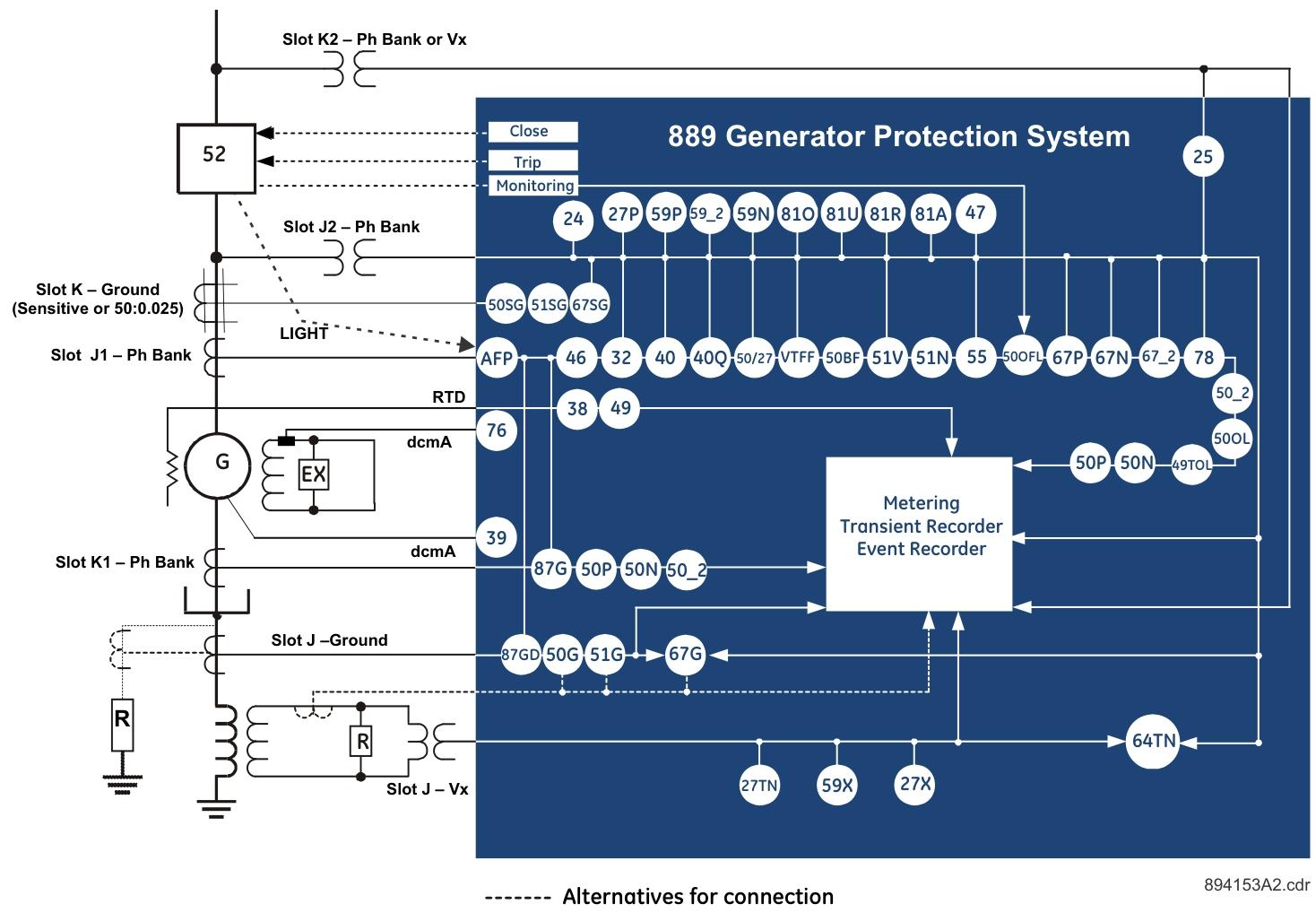
Protection function: covering various protection elements such as percentage differential protection, overcurrent, overvoltage/undervoltage, frequency abnormality, demagnetization, reverse power, etc. (see ANSI equipment numbering table for details).
Flexibility: Supports custom logic (FlexLogic), programmable curves (FlexCurve), multiple sets of setpoints, and default settings simplify initial configuration.
Monitoring and recording: Real time monitoring of parameters such as current, voltage, and power, with functions such as event recorder (1024 events), transient recorder (waveform capture), and fault report (15 events).
Communication capability: Supports multiple protocols such as Modbus, DNP3.0, IEC 60870-5-103/104, IEC 61850, etc., with optional interfaces such as Ethernet, RS485, Wi Fi, etc.
Installation instructions
1. Mechanical installation
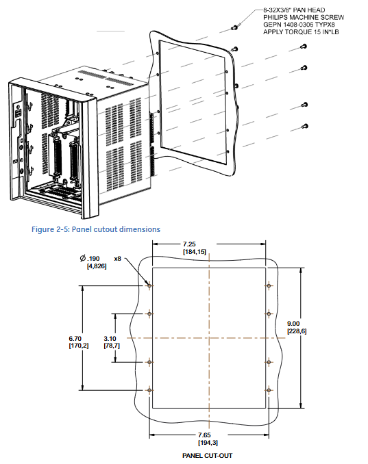
Size and installation method: Supports standard panel installation, drawer installation, and can be matched with a depth reducing ring to adapt to narrow spaces; The full-size weight is about 9kg, and ventilation gaps need to be reserved at the top and bottom.
Key component installation: The power module and magnetic module (CT/VT) need to be plugged and unplugged according to the steps. Before removing the magnetic module, the system power must be disconnected and the CT secondary side short circuited to prevent high voltage hazards.
Installation of arc light sensor: The optical fiber should avoid bending with a radius less than 25mm, and the installation position should be unobstructed. It supports 4 point sensors and has a standard fiber length of 18 feet (maximum 32 feet).
2. Electrical installation
CT/VT connection: CT supports 1A/5A secondary, VT supports star/triangle connection, pay attention to phase sequence and polarity to ensure correct protection function.
Grounding requirements: The system rack, EMI shielding, and cables must be reliably grounded, and the grounding resistance of the intrinsic safety system must be<1 Ω.
Wiring specifications: The control power supply should match the rated range (such as 110-250V AC/DC), and the communication line should use shielded twisted pair. The maximum distance of RS485 is 1200 meters.
Interface Description
1. Front panel interface
Display screen and buttons: graphic LCD display, supports menu navigation (Targets, Status, Metering, etc.), 5 navigation keys+3 programmable function keys, 17 LEDs (including programmable status indication).
Operation function: It can view real-time data, set parameters, reset alarms, support single line diagram (SLD) display, and can configure default screens and color schemes.
2. Software interface (EnerVista 8 Series Setup)
Function: Used for configuring parameters, upgrading firmware, viewing records, drawing custom SLDs, etc., supporting online/offline operations.
Connection method: Connect via USB, Ethernet, Wi Fi, and configure communication parameters such as IP address and port.
Advanced features: SLD configurator (custom single circuit diagram), FlexCurve editor (custom protection curve), transient recorder (waveform analysis), etc.
Detailed explanation of core functions
1. Protection function
Differential protection: including generator stator differential (87G), overall differential (87O), supporting dual slope characteristics, 2nd/5th harmonic braking.
Overcurrent protection: including phase/neutral/ground overcurrent (50/51 series), supporting multiple inverse time curves (IEEE, IEC, etc.).
Voltage protection: Over/Under voltage (59/27 series), Negative sequence overvoltage (59_2), Voltage Hertz protection (24), etc.
Other protections: demagnetization (40), reverse power (32), abnormal frequency (81U/O/R), arc protection (AFP), etc.
2. Monitoring function
Real time monitoring: current, voltage, power, frequency, harmonics, temperature (RTD), etc., with an accuracy of ± 0.25% (current) and ± 0.5% (voltage).
Recording function: Event recording (timestamp accurate to microseconds), transient recording (waveform before and after fault), data log (configurable with 16 analog quantities).
3. Control function
Circuit breaker control: supports opening/closing, locking, and bypass, adopts the "select first, operate later" mechanism, and is compatible with local/remote control.
Synchronization check (25): Monitor voltage, frequency, and phase difference to ensure that the grid connection conditions are met.
Arc protection: Detecting arc light through fiber optic sensors, quickly triggering tripping, and reducing equipment damage.
Set point configuration
Device settings: including clock synchronization (IRIG-B, PTP, SNTP), security (user roles, password policies), and communication protocol parameters.
System settings: CT/VT parameters, generator rating, grounding method, etc.
Input/output settings: Configure analog input (such as 4-20mA), digital input (wet/dry contacts), and output relay (trip/alarm).
Protection settings: Threshold, delay, action mode (trip/alarm), etc. of each protection element, supporting multiple sets of setting point switching.
Specifications and Safety
Environmental parameters: Operating temperature -40 ° C to 60 ° C, humidity 0-95%, no condensation, seismic rating IEC 60255-21-3 Class 2.
Safety certification: CE, UL508, ISO 9001, etc., in compliance with EMC standards (EN 61000 series).
Warning: Before operation, the dangerous voltage must be disconnected, and the CT secondary side must not be open circuited. Suitable personal protective equipment must be used.
- OMRON
- ABB
- General Electric
- EMERSON
- Honeywell
- HIMA
- ALSTOM
- Rolls-Royce
- MOTOROLA
- Rockwell
- Siemens
- Woodward
- YOKOGAWA
- FOXBORO
- KOLLMORGEN
- MOOG
- KB
- YAMAHA
- BENDER
- TEKTRONIX
- Westinghouse
- AMAT
- AB
- XYCOM
- Yaskawa
- B&R
- Schneider
- KONGSBERG
- NI
- WATLOW
- ProSoft
- SEW
- ADVANCED
- Reliance
- TRICONEX
- METSO
- MAN
- Advantest
- STUDER
- DANAHER MOTION
- Bently
- Galil
- EATON
- MOLEX
- DEIF
- B&W
- ZYGO
- Aerotech
- DANFOSS
- Beijer
- Moxa
- Rexroth
- Johnson
- WAGO
- TOSHIBA
- BMCM
- SMC
- HITACHI
- HIRSCHMANN
- Application field
- XP POWER
- CTI
- TRICON
- STOBER
- Thinklogical
- Horner Automation
- Meggitt
- Fanuc
- Baldor
- SHINKAWA
- Other Brands
- UniOP
- KUKA
- Iba
- Beckhoff
- ADLINK
-
 Sigmatek MDD111-1 DIAS Drive Axis Module
 -
 Sigmatek DKL042 05-024-042 Terminal Module
 -
 Sigmatek DM822 Control Module
 -
 Sigmatek CDM167 12-008-167-O Module
 -
 Sigmatek TAE151 Touch Display Unit
 -
 Sigmatek DCC041 SLIDES Module 05-700-041-D
 -
 Sigmatek AKM65M-ANC2GBB0 PM Servo Motor
 -
 Sigmatek ETT221 01-230-221 Operator Terminal
 -
 Sigmatek SLIDES DAM 124 Analog Module
 -
Sigmatek AKM31C-ANCNGBB0 Servo Motor
-
 Mannesmann Demag Sigmatek CP626 Central Unit
 -
 SIGMATEK 0332.554.03 Board 371071000154
 -
 SIGMATEK 12-250-021 Base Plate Back Panel CM5V020
 -
 SIGMATEK DM162 S-DIAS Digital Mix Module
 -
 DEMAG ERGOTECH 061 381 66 Sigmatek 9842.243.02 Circuit Board
 -
 SIGMATEK CP313-1 PLC Module
 -
Sigmatek ETV0551-2 VARAN Touch Terminal
-
 Sigmatek SDM 081 FS S-Dias Safety Module
 -
 DEMAG 05-250-023 Ergotech Motherboard with Sigmatek TMS012
 -
Sigmatek CM5V020 12-250-023-K Wiring Base
-
 Sigma Tek 5000B-37 Attitude Gyro Indicator
 -
 Sigmatek SDD120-2 DIAS Drive
 -
 Sigmatek CME221 Memory Module
 -
 Sigmatek DCP640 DIAS Central Unit
 -
 Sigmatek STO040 Safety Output Module
 -
Sigmatek CET281 Control Panel
-
 Sigmatek CIPC LX800 Demag NC5 CPU
 -
 Sigmatek DKL093 05-024-093 Terminal Module
 -
 Sigmatek AI088 20-009-088 Analog Input Module
 -
Sigmatek CAI888 Analog Input Module
-
SIGMATEK CCA021 12-025-021 Analog Output Module
-
SIGMATEK 1104.579.05 Control Module
-
SIGMATEK SDI100 Digital Input Module
-
 SIGMATEK C-IPC 256MB LX800 Compact Dias
 -
 SIGMATEK 9423.090.02 Control Module
 -
SIGMATEK C-IPC 256 Power Supply 148498
-
 SIGMATEK CAI025 Analog Input Module
 -
 SIGMATEK CTO166 Digital Output Module
 -
 SIGMATEK CP112 20-004-112 Processor Module
 -
SIGMATEK CAI887 12-009-887 Safety Module
-
 Sigma-Tek 4000B-31 Directional Gyro 1U262-002-42
 -
Sigmatek C-IPC 256MB LX800 IPC Controller
-
Sigmatek C-IPC 01-450-031 Industrial PC LX800
-
Sigmatek C-IPC 256 Industrial PC Controller
-
Sigmatek CCP-531 PLC Processor Module
-
Sigmatek CDI163 Digital Input Module
-
 Sigmatek ETV0501 VARAN Terminal 12-230-0501
 -
 Sigmatek CTMS020 C-DIAS Technology Module
 -
 Sigmatek CIV512 VARAN Switch Module
 -
 Sigmatek HU011 20-080-011 Interface Module
 -
SIGMATEK SLIDES DAM 124 Module
-
 SIGMATEK C-IPC 161 01-450-161L Industrial PC
 -
SIGMATEK C-IPC 128MB VIA 733MHz 01-450-024-K
-
 SIGMATEK 12-780-012 R8-IPC Geode LX800 Module
 -
SIGMATEK CAM124 Analog Module
-
 SIGMATEK S1 032-8AF61-R4 EZ Servo Motor
 -
 SIGMATEK CTO163 Digital Output Module
 -
 SIGMATEK CCP082 12-004-082 Processor Module
 -
 SIGMATEK CRCH081 C-DIAS Temperature Module
 -
 SIGMATEK PC322-K 01-310-322-K Industrial PC
 -
SIGMATEK SDD310-2 Servo Drive
-
 SIGMATEK AI084 Analog Input Module
 -
SIGMATEK CRCH081 12-752-081 Temperature Module
-
Sigma-Tek 5000L-4 Attitude Gyro 1U284-001-3
-
 SIGMATEK CM5V020 12-250-023-K Wiring Module
 -
Sigma-Tek 4000H-6 Directional Gyro IU262-035-7
-
 SIGMATEK Dias DCP160 05-004-160 Processor Module
 -
SIGMATEK 0147.395.02 Control Module
-
SIGMATEK A1084 Control Module
-
SIGMATEK DI200 20-006-2000 Digital Input Module
-
Sigmatek DNC115 Encoder Module
-
 Sigmatek DAM122 05-017-122 Analog Module
 -
Sigmatek 9802.289.01 Control Board TA71 Display
-
Sigmatek TO127 20-007-127 Digital Output Module
-
Sigmatek DNC031 05-011-031 Digital Module
-
Sigmatek VI022 20-003-022 Interface Module
-
Sigmatek CAI085 Analog Input Module
-
 Sigmatek CP111 S-DIAS CPU Module
 -
Sigmatek CTMS030 Krauss Maffei Module
-
 Sigmatek CAM123 Control Module
 -
 Sigmatek TAE732-P 01-240-732-P Touch Display Unit
 -
Sigmatek MDM021 Digital Mixed Module
-
Sigmatek DCP642 DIAS Central Unit
-
 Sigmatek CST022 12-014-022 C-DIAS Module
 -
 Sigmatek SRO021 20-893-021 Safety Relay Output
 -
 Krauss Maffei MC5 Control System Sigmatek
 -
 Sigmatek DC061 Module 18-24VDC 300mA
 -
 Herrmann EVT0855 Ultrasonic Welder Touch Panel
 -
Sigmatek CIV521 Control Module 1.4A 2W
-
Sigmatek DDI61 05-006-161 Digital Input Module
-
SIGMATEK ETT312-E Touch Terminal 01-230-312
-
Cessna S3326-1 Sigma Tek 5000B-67 Gyro 1U149-015-9
-
SIGMATEK PS101 Power Supply Module
-
SIGMATEK 0332.554.03 Control Module 371071000154
-
 SIGMATEK ETT312-E Touch Terminal 01-230-312
 -
SIGMATEK CDM163 Control Module
-
 SIGMATEK VSV046 16-023-046 Module
 -
SIGMATEK AM221 20-017-221 Analog Module
-
SIGMATEK CTS051 12-053-051 Control Module
-
SIGMATEK AM221 20-017-221 Analog Module
-
Sigmatek CSDI161 12-891-161 Safety Input Module
-
Sigma Tek 4000C-1 Directional Gyro Indicator
-
Sigmatek ETV0501 12-230-0501 VARAN Terminal
-
Sigmatek DDM165 SLIDES Module
-
Sigmatek N100 20-011-100 Control Module
-
Sigmatek AKM54K-ANC2R-B0 PM Servo Motor
-
Sigmatek CTO166 Digital Output Module
-
Sigmatek CP212-K 20-004-212-K CPU Module
-
Sigmatek CDI161 Digital Input Module
-
Sigmatek DCC080 05-700-080-2 Control Module
-
 SIGMATEK SCP011 S-DIAS Safety CPU
 -
SIGMATEK SCP011 S-DIAS Safety CPU
-
SIGMATEK SRO022 Relay Output Module
-
SIGMATEK MDD 121 Drive Axis Module
-
SIGMATEK DSI021 SLIDES Siemens Interface
-
SIGMATEK DIAS DCP161 Module 05-004-161
-
 Sigmatek ETT312 Built-in Touch Terminal
 -
SIGMATEK DCP 643 DIAS Controller System
-
SIGMATEK CIO021 Multi I/O Module
-
SIGMATEK CTMS020 Control Module
-
 Sigmatek CME 221 Memory Module
 -
Sigmatek 0420.615.01 Control Board
-
Sigmatek CP111 20-004-111 CPU Module
-
Sigmatek 9405.065.03 Control Board
-
Sigmatek ETEK 01-450-032-K C-IPC 256MB Industrial PC
-
Sigmatek CTO163 12-007-163 Safety Output Module
-
Sigmatek TO081 20-007-081 Digital Output Module
-
 Sigmatek SI021 20-022-021 Safety Input Module


