
YASKAWA S-7 series linear servo
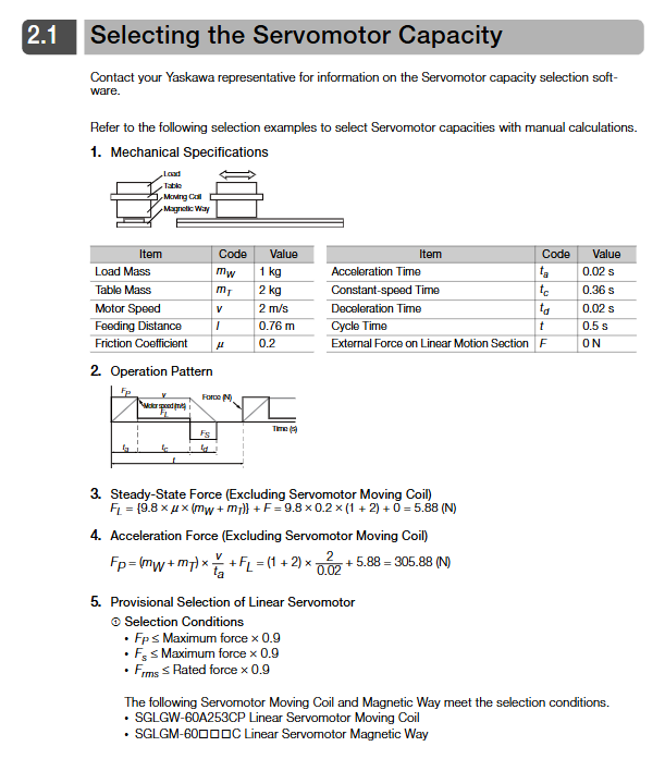
Cleaning requirements: The installation area should be free of dust and metal shavings, and lubricating oil should not be applied to the surface of the magnetic track.
(2) Magnetic track installation operation
Positioning and fixation:
Single segment magnetic track: placed on the equipment positioning platform, with the reference mark (4mm diameter pit) facing the equipment, fixed with a 10.9 grade hex socket screw, tightening torque 3.6-41.5N · m (according to the model: SGLG uses M4 screws, torque 3.6-5.0N · m; SGLT uses M8 screws, torque 29.7-41.5N · m);
Multi segment magnetic track: The distance between adjacent magnetic tracks should be ≥ 30mm, aligned with reference marks, and the gap at the connection should be ≤ 0.1mm to avoid thrust fluctuations.
Gap calibration: The gap between the magnetic track and the rotor should be uniform, measured with a non-magnetic feeler gauge, with an error of ≤± 0.3mm (SGLG series gap 0.8 ± 0.3mm, SGLT series gap 1.0 ± 0.3mm).
(3) Assembly process of moving parts
Preprocessing: Check for cracks in the rotor winding and plastic casing, and ensure that the polarity sensor plug is not damaged;
Fixed rotor: Fix the rotor to the workbench with M4-M8 level screws, with a screw fit length of ≥ 4mm and a tightening torque of 2.4-20N · m (SGLG uses M4 screws with a torque of 2.4N · m; SGLF uses M8 screws with a torque of 20N · m);
Approaching the magnetic track: Slowly move the worktable to bring the rotor closer to the magnetic track, and monitor for any frictional noise during the process;
Gap verification: Insert a 0.8-1.4mm non-magnetic feeler gauge into the gap between the rotor and the magnetic track to ensure uniform clearance throughout the entire stroke;
Cable fixation: The movable cable is fixed in the direction of the worktable movement, with a bending radius of ≥ 15mm (cable diameter<8mm) or ≥ cable diameter × 3 (cable diameter>8mm), to avoid pulling and causing breakage.
(4) Special requirements for water-cooled models (SGLFW2-90A series)
Cooling medium: Deionized water, pH 6.8-8.0, conductivity ≤ 30mS/m, chloride ion content ≤ 50mg/L, no oil stains or impurities;
Flow and pressure: rated flow rate 4L/min, maximum flow rate 6L/min, working pressure ≤ 0.5MPa, instantaneous pressure ≤ 1.0MPa;
Pipeline installation:
Pipeline material: stainless steel or corrosion-resistant plastic, with Rc1/8 tapered pipe thread joints, wrapped with sealing tape to prevent water leakage;
Filtering and protection: Install a ≥ 0.5mm impurity filter at the inlet, and keep the pipeline away from high-temperature components (such as motor windings);
Maintenance requirement: Drain the accumulated water in the pipeline during long-term shutdown to avoid icing damage.
2. Electrical installation specifications
(1) Wiring sequence and principles
Wiring sequence: First connect the servo main circuit cable (U/V/W/FG), then connect the encoder cable, and finally connect the sensor cable (polarity sensor/thermal protector). Live wiring is prohibited;
Grounding requirements:
Ground resistance of servo amplifier: 400V level ≤ 10 Ω, 200V level ≤ 100 Ω;
Motor grounding: The FG terminal is connected to the protective grounding of the equipment, and the cross-section of the grounding wire is ≥ 10mm ² (copper core). The shielding layer is grounded at one end (amplifier side);
Cable separation: The distance between the power cable (main circuit) and the signal cable (encoder/sensor) should be ≥ 30cm. It is forbidden to wire or bundle them in the same pipe to avoid electromagnetic interference.
(2) Core cable selection and connection
Cable type, usage, length limit, recommended model, connection requirements
Servo main circuit cable transmission motor power supply ≤ 20 meters JZSP-CLN11 (SGLG), JZSP-CLN21 (SGLF), JZSP-CLN39 (SGLT) phase U (red), V (white), W (blue) corresponding connection, FG (green yellow) grounding
Encoder cable transmission position detection signal ≤ 50 meters JZSP-CLL00 (Renishaw encoder), JZSP-CLL30 (Heidenhain encoder) shielded twisted pair, away from power cables, with firm and secure joints without looseness
Sensor cable transmission polarity sensor/thermal protector signal ≤ 15 meters JZSP-CLL10 (regular model), JZSP-CL2L100 (model with thermal protector) polarity sensor+5V (red), 0V (black), signal terminal (white/blue) corresponding connection
(3) Serial conversion unit (JZDP series) connection
Function: Convert the sine/cosine signal of the linear encoder into a digital signal, transmit it to the servo amplifier, and receive signals from the polarity sensor and thermal protector;
Power supply requirements: Power supply+5V ± 5%, current consumption ≤ 160mA (excluding encoder and sensor currents);
Signal requirement: Analog input signal amplitude 0.4-1.2V, differential input, to avoid signal attenuation.
Safety regulations and compliance standards
1. Core security requirements
(1) Electrical safety
Power off operation: Disconnect all power sources before maintenance, wait for the servo amplifier CHARGE indicator light to turn off (≥ 5 minutes), use a multimeter to confirm that the main circuit voltage is ≤ 50Vdc before operation;
- OMRON
- ABB
- General Electric
- EMERSON
- Honeywell
- HIMA
- ALSTOM
- Rolls-Royce
- MOTOROLA
- Rockwell
- Siemens
- Woodward
- YOKOGAWA
- FOXBORO
- KOLLMORGEN
- MOOG
- KB
- YAMAHA
- BENDER
- TEKTRONIX
- Westinghouse
- AMAT
- AB
- XYCOM
- Yaskawa
- B&R
- Schneider
- KONGSBERG
- NI
- WATLOW
- ProSoft
- SEW
- ADVANCED
- Reliance
- TRICONEX
- METSO
- MAN
- Advantest
- STUDER
- DANAHER MOTION
- Bently
- Galil
- EATON
- MOLEX
- DEIF
- B&W
- ZYGO
- Aerotech
- DANFOSS
- Beijer
- Moxa
- Rexroth
- Johnson
- WAGO
- TOSHIBA
- BMCM
- SMC
- HITACHI
- HIRSCHMANN
- Application field
- XP POWER
- CTI
- TRICON
- STOBER
- Thinklogical
- Horner Automation
- Meggitt
- Fanuc
- Baldor
- SHINKAWA
- Other Brands
- UniOP
- KUKA
- Iba
- Beckhoff
-
 Basler DECS-200-2L Digital Excitation Control
 -
 Basler BE1-47N Voltage Phase Sequence Relay
 -
 Basler AEC63-7 Analog Excitation Controller 220-277V
 -
 Basler BE1-50/51B-107 Overcurrent Relay
 -
 Basler Electric BE1‑32R BE1‑E1P‑BON0F Protective Relay
 -
 Basler BE1-25 Solid State Time Overcurrent Relay M1EA6PA5S1F
 -
 Basler MVC 232 Manual Voltage Control Module 90 37000 103 60VAC 55VDC
 -
 Basler RAL6144-16GM Racer GigE Line Scan Camera
 -
 Basler SSR 63-12 Static Voltage Regulator
 -
 Basler BE1-51A Overcurrent Relay
 -
 Basler BE1-87T Solid State Protective Relay
 -
 Basler SR4A2B01B3A Static Voltage Regulator
 -
 Basler SSR 32-12 Static Voltage Regulator
 -
 Basler TRR00696 Transformer 1KVA 115V
 -
 Basler DECS-100-B15 AVR Replacement
 -
Basler BE1-27 Under-Voltage Relay
-
 Basler ACA2000-50GM Interface Module
 -
 Basler AEC63-7 Analog Excitation Controller
 -
 Basler PRS 250 Veri-Sync Relay
 -
 Basler SR4A-2B15B3A Static Voltage Regulator
 -
Basler BE1-32R Power Relay
-
Basler SR8A-2B06B3E Static Voltage Regulator
-
Basler BE1-81 O/U Frequency Relay
-
 Basler BE1-51A-K2E-W6M-B1N0F Overcurrent Relay
 -
Basler BE1-851 Overcurrent Relay G3A1S1 – 48-125V AC/DC
-
 Basler BEI-51 Overcurrent Relay – NSN 5945-01-293-2363
 -
Basler Electric L301KC Protective Relay – L301KC
-
 Basler DECS-100-B15 Automatic Voltage Regulator – Generator AVR
 -
 Basler SR4A-2B15B3A Static Voltage Regulator – SR4A2B15B3A
 -
 Basler UF 312 Under Frequency Protective Module – 9094700100
 -
Basler Electric MVC 232 Manual Control Module – 60VAC 55VDC 20A
-
Basler PRS 250 Veri-Sync Relay – Generator Synchronizing Relay
-
 Basler DECS-100-A05 Digital Regulator Review
 -
 Basler AEM-2020 Analog Expansion Module Specs
 -
 Basler DECS-100-B15 Digital Excitation Specs
 -
Basler Electric 9125600106 Regulator Component
-
Basler BE1-51A-K1E-W6M-B1N0F Overcurrent Relay
-
 Basler MVC-301 MVC 300 Excitation Controller
 -
 Basler SSR 32-12 Static Voltage Regulator
 -
 Basler 9-2849-00-101 Control Module
 -
Basler BE1-51A Overcurrent Relay
-
 Basler BE1-51/27R Overcurrent Relay
 -
 Basler BE1-51 Overcurrent Relay
 -
 Basler SR8A-2B15B3A Static Voltage Regulator
 -
 Basler BE32965001 Transformer and Timer Board
 -
 Basler 9174700100 EL200-7 Excitation Limiter
 -
 Basler BE2000E AVR Voltage Regulator
 -
Basler BE1-87G Differential Relay
-
 Basler BE21834001 Generator Control Module
 -
Basler DECS-100-B15 AVR
-
 Basler D90 96801 100 PCB Card
 -
 Basler XR2002F Voltage Regulator (110 VAC, 48-480 Hz)
 -
 Basler SR8A-2B14B3A Regulator
 -
 Basler 9561500100 Module
 -
 Basler DECS-400 BE1-11 System
 -
 Basler DECS-100-B15 Excitation Control
 -
 Basler SCP 210 Frequency Controller
 -
Basler SR4A-2B15B3A Static Voltage Regulator
-
Basler BE1-32R Power Relay
-
 Basler PIA2400-17GM Power Interface Adapter
 -
 Basler MVC 232 Manual Voltage Control Module
 -
 Basler SSR 32-12 Static Voltage Regulator
 -
Basler 5MW AVR Generator Voltage Regulator
-
 Basler VR63-4B Voltage Regulator
 -
Basler DECS-100-A05 AVR for Engine Generator
-
Basler DECS-100-B15 Automatic Voltage Regulator
-
Basler BE1-32R Directional Power Relay
-
Basler BE1-87B Differential Relay
-
 Basler UFOV 260A Protective Module
 -
 Basler 9-2614-02-100 PCB Rev M
 -
Basler DECS-100-B15 Digital AVR
-
 Basler 9284900103 PS DECS-400N
 -
 Basler D4N3H1U Intertie Protection
 -
 Basler DECS-100-B15 A15 AVR
 -
 Basler KR4F Voltage Regulator
 -
 Basler BE26434 T14 Transformer
 -
 Basler SR8A-2B15B3A Regulator
 -
 Westinghouse 774B472A12 AR Relay
 -
Basler DECS-100-B15 AVR
-
Basler XR2002F Regulator 110V
-
Basler SR125-E Static Regulator
-
Basler SSR 125-12 Regulator
-
Basler MOC2599 Motor Pot
-
 Basler BE1-DFPR Feeder Relay
 -
 Basler CBS 305 Current Boost
 -
Basler BE1-25 AutoSync
-
Basler MVC 300 Voltage Control
-
 Basler BE3-25A AutoSync
 -
 Basler KR7FF Static Regulator
 -
Basler 90-49000-100 Regulator
-
 Basler 880 kVA Dry Type Transformer Specs
 -
Basler Electric BE1-25 Sync-Check Relay Specs
-
 Basler SSR 125-12 Voltage Regulator Specs
 -
 Basler Electric BE1-851 Overcurrent Relay Review
 -
Basler Electric 149D930G02 Control Sub-Assembly
-
 Basler Electric BE1-81O/UT Frequency Relay Specs
 -
 Basler Electric BE1-51/27C Overcurrent Relay
 -
 Basler Electric 149D956G02 Industrial Component
 -
Basler Electric BE1-51A Overcurrent Relay Specs
-
 Basler Electric BE1-40Q Loss of Excitation Relay
 -
Basler DECS-200 Excitation Control System
-
 Basler DECS-200 Voltage Regulator 56-277V AC / 125V DC
 -
Basler BE1-87T Transformer Differential Relay
-
 Basler RDP-110-S1 Protection Relay
 -
 Basler BE1-700V Digital Protective Relay
 -
 Basler BE1-951 Overcurrent Protection System
 -
 Basler DECS-300 Digital Excitation Control
 -
 Basler DECS-200 Digital Excitation Control
 -
 Basler DECS-200-1C Excitation Control System
 -
Basler DECS-200-1L Digital Excitation Control
-
 Basler Electric BE1-GPS Generator Protection System
 -
Basler Electric DECS-200-1C Digital Excitation Controller
-
 Basler Electric DECS125-15 Excitation Control with Power Module
 -
Basler Electric BE1-87G Differential Relay
-
 Basler Electric BE1-11 Protection System I5A3M2P2N0EA00
 -
Basler Electric DECS-200-1C Excitation Control System
-
Basler Electric BE1-11g Generator Protection Relay
-
Basler Electric DECS 125-15-B2C1 V2.0.9 Excitation Control
-
Basler Electric BE1-81O/UT3ED1JA7N2F Frequency Relay
-
Basler Electric BE1-81O/UT3EE1YB7N1F Frequency Relay
-
 Basler Electric DECS-200-1L Digital Excitation Control System
 -
Basler DECS125-15-B2C1 Excitation Control
-
 Basler 9507900205 SSR Retrofit Voltage Regulator
 -
 Basler BE2000E Digital Voltage Regulator
 -
 Basler BE1-GPS Generator Protection System
 -
Basler DECS-250-CN1CN1N Digital Excitation Control
-
 Basler DGC-2020 Genset Controller
 -
Basler BE1-81O UT3ED1LA7N0F Frequency Relay (Variant)


