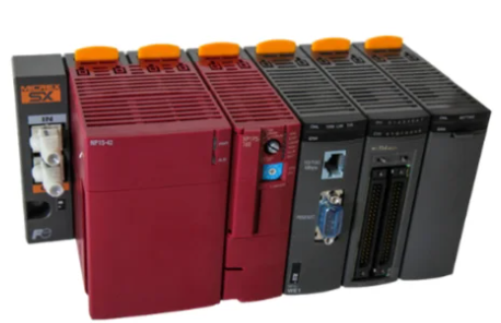
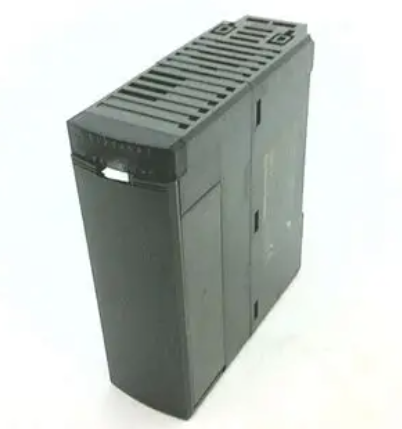
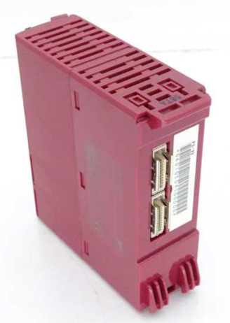
YOKOGAWA FA-M3 positioning module (with analog voltage output)
Document identification: Document number IM 34M6H58-01E, document model code DOCIM. This number must be referenced for communication and additional manual purchases; The media number is the same as the document number (CD version), and the copyright belongs to Yokogawa Electric in 1998.
Origin search can be defined through the origin setting value and external triggering; Search speed: Users can set the same single axis-
External contact input limit switch, driver alarm, origin, external trigger, universal input, emergency stop contact are the same as single axis 24V DC, 4.1mA
External contact output servo ON, driver reset, brake OFF contacts are the same as single axis 24V DC, 0.1A
Data backup is handled by the CPU module on the same single axis-
Start time maximum 6ms maximum 6ms-
Current consumption 5V DC, 390mA 5V DC, 400mA-
External power supply 24V DC, 10mA 24V DC, 10mA-
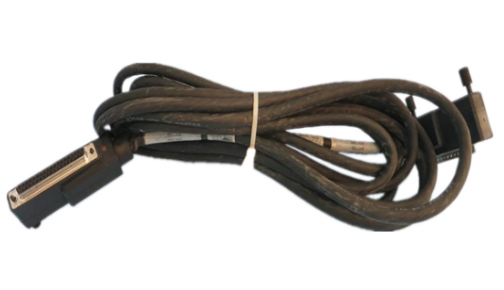
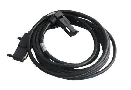
External wiring 40 pin connector (1) 40 pin connector (2)-
Dimensions: 28.9 (width) x 100 (height) x 83.2 (depth) mm (excluding protrusions) Same as single axis-
Weight 130g 140g-
2. Model and suffix code
Model code suffix code type remarks
F3NC51-0N single axis position loop control, -10~10V voltage output, maximum speed 2Mpps
F3NC52-0N dual axis position loop control, -10~10V voltage output, maximum speed 2Mpps
3. Applicable encoders
Universal two-phase rotary encoder;
Yokogawa Motor serial absolute encoder (such as ∑ series);
Sanyo Motor serial absolute encoder (such as P series) or compatible models (such as Panasonic MINAS series, Manchester encoded serial transmission).
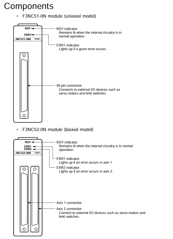
4. Module components and indicator lights
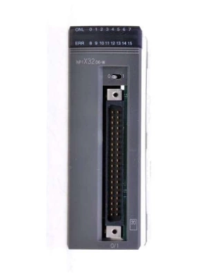
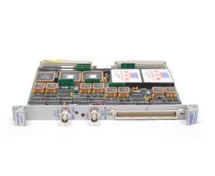
F3NC51-0N (single axis): RDY indicator light (always on when the internal circuit is normal), ERR1 indicator light (lit when an error occurs), 40 pin connector (connected to external I/O devices such as servo motors and limit switches).
F3NC52-0N (dual axis): RDY indicator light (normally lit), ERR1 indicator light (lit up for axis 1 error), ERR2 indicator light (lit up for axis 2 error), 2 40 pin connectors (corresponding to external device connections for axis 1 and axis 2 respectively).
Function Overview
The core functions of the module revolve around the position control, speed control, and mode switching of the motor, supporting various flexible operations, as follows:
Function Name Core Description Operation Points
The positioning operation is performed according to the instructions of the CPU module. After setting the target position, speed, acceleration and deceleration parameters, the "start operation instruction" relay is triggered. After the positioning is completed, the "positioning end" relay can be set to absolute/relative position; The acceleration and deceleration curves can be trapezoidal, two-stage, or S-shaped; Can set the positioning judgment range and timeout period; Support normal startup or waiting for internal/external trigger startup
Target position change during positioning operation, writing new positioning parameters and triggering the "Target Position Change Request" relay, can synchronously change speed, supports direction change (motor first stops urgently and then locates towards the new target position)-
Speed change during positioning operation, writing new target speed and triggering the "speed change request" relay to achieve real-time speed adjustment-
Speed control writes parameters such as target speed (negative speed corresponds to reverse rotation), acceleration and deceleration time, triggering the "start operation command" relay. The motor continues to rotate and needs to be terminated through "deceleration stop request" or "immediate stop request". Only incremental encoders are supported; Acceleration and deceleration curves are the same as positioning operations; Support normal startup or waiting for internal/external trigger startup
Speed change in speed control. During speed control operation, writing a new target speed and triggering the "speed change request" relay does not support direction change (need to slow down and stop first, then reset direction to start)-
Switching between speed and position control modes: During the operation of speed control, parameters such as target position, speed, acceleration and deceleration are written to trigger the mode switching command. The positioning operation can be set to normal switching or wait for external triggering switching when the instantaneous position is set to "0"; Support detection of Z-phase signal switching (Z-phase polarity and counting frequency need to be set)
Writing parameters such as target speed and acceleration/deceleration time in jog step, triggering the "positive jog step" or "negative jog step" relay. When the relay is disconnected, the motor decelerates and stops according to the parameters, which only takes effect when there are no errors, servo ON, positioning end, position control mode, and no other instructions are executed; Can only be terminated by "stop immediately", cannot be stopped by "slow down"
The emergency stop input module includes one emergency stop input (dedicated to the 1-axis connector, shared by both axes), which is a B-contact input and must be wired. Otherwise, the module will not work and the motor will stop immediately after triggering-
External contact input: 6 external contact inputs, functions can be defined through the "contact input mode" (such as limit, alarm, origin, trigger, etc.), polarity can be set separately, and status can be read through the application program-
- EMERSON
- Honeywell
- CTI
- Rolls-Royce
- General Electric
- Woodward
- Yaskawa
- xYCOM
- Motorola
- Siemens
- Rockwell
- ABB
- B&R
- HIMA
- Construction site
- electricity
- Automobile market
- PLC
- DCS
- Motor drivers
- VSD
- Implications
- cement
- CO2
- CEM
- methane
- Artificial intelligence
- Titanic
- Solar energy
- Hydrogen fuel cell
- Hydrogen and fuel cells
- Hydrogen and oxygen fuel cells
- tyre
- Chemical fiber
- dynamo
- corpuscle
- Pulp and paper
- printing
- fossil
- FANUC
- Food and beverage
- Life science
- Sewage treatment
- Personal care
- electricity
- boats
- infrastructure
- Automobile industry
- metallurgy
- Nuclear power generation
- Geothermal power generation
- Water and wastewater
- Infrastructure construction
- Mine hazard
- steel
- papermaking
- Natural gas industry
- Infrastructure construction
- Power and energy
- Rubber and plastic
- Renewable energy
- pharmacy
- mining
- Plastic industry
- Schneider
- Kongsberg
- NI
- Wind energy
- International petroleum
- International new energy network
- gas
- WATLOW
- ProSoft
- SEW
- wind
- ADVANCED
- Reliance
- YOKOGAWA
- TRICONEX
- FOXBORO
- METSO
- MAN
- Advantest
- ADVANCED
- ALSTOM
- Control Wave
- AB
- AMAT
- STUDER
- KONGSBERG
- MOTOROLA
- DANAHER MOTION
- Bently
- Galil
- EATON
- MOLEX
- Triconex
- DEIF
- B&W
- ZYGO
- Aerotech
- DANFOSS
- KOLLMORGEN
- Beijer
- Endress+Hauser
- MOOG
- KB
- Moxa
- Rexroth
- YAMAHA
- Johnson
- Westinghouse
- WAGO
- TOSHIBA
- TEKTRONIX


Email:wang@kongjiangauto.com

