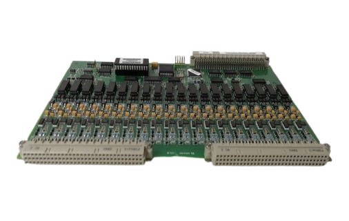
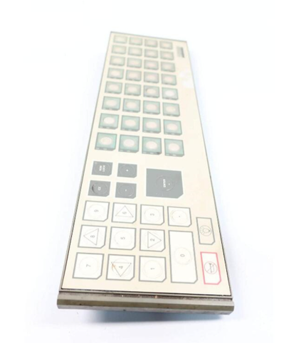
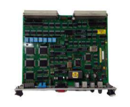
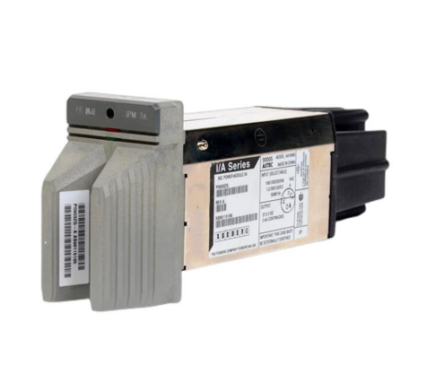
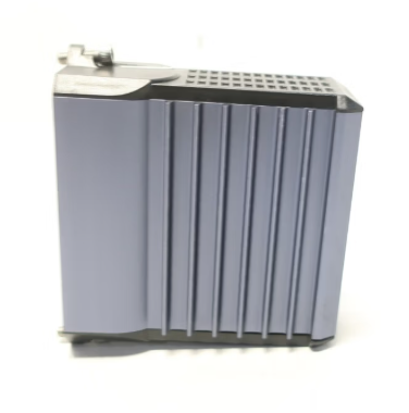
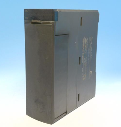
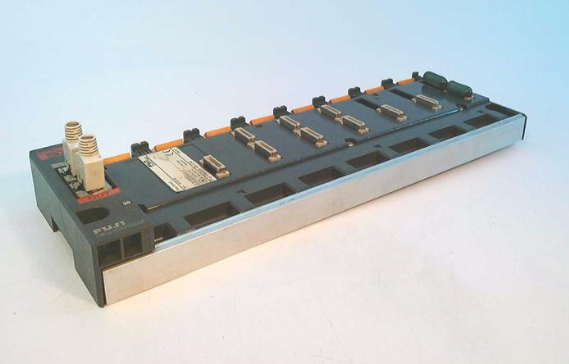
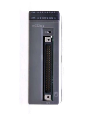
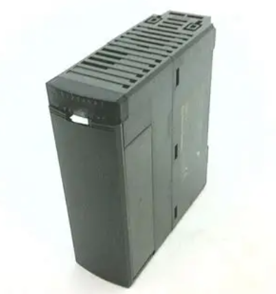
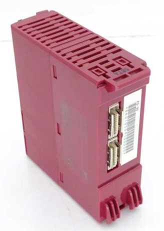
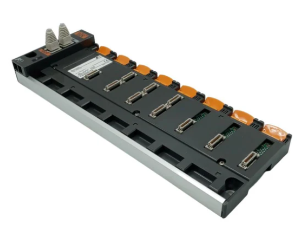
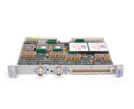
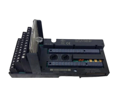
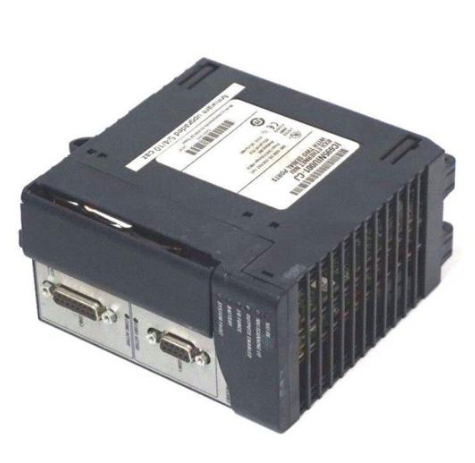
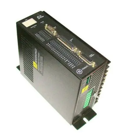
YOKOGAWA FA-M3 positioning module (with analog voltage output)
Document identification: Document number IM 34M6H58-01E, document model code DOCIM. This number must be referenced for communication and additional manual purchases; The media number is the same as the document number (CD version), and the copyright belongs to Yokogawa Electric in 1998.
Error codes and servo parameter adjustment
1. Classification and Handling of Error Codes
Module errors are divided into servo errors (related to motor motion, servo OFF triggered), parameter errors (invalid parameters during instruction execution, triggering error notifications), and parameter setting errors (invalid parameters during parameter setting, requiring rewriting of correct parameters). The core error codes are as follows:
Error type code, error description, handling suggestions
Servo error 12 driver alarm input detected. Check the cause of the driver alarm and perform error reset after resetting the driver
Servo error 13/14: Positive/negative limit input detected. Check the direction of motor operation and limit switch status to eliminate mechanical obstruction
Servo error 17/18 detected overspeed/over acceleration. Adjust the "overspeed detection value"/"over acceleration detection value" parameters to ensure that a buffer is left
Servo error 19: Deviation error detected. Check the position loop gain, speed feedforward coefficient, or adjust the "deviation error detection value"
Servo error 9999: Emergency stop triggered, execute error reset after releasing the emergency stop state
Parameter error: 10xx parameter is invalid (xx is the lower 2 bits of the parameter data position). Check if the corresponding parameter value is within the valid range and rewrite the correct value
Parameter setting error: 20xx Parameter setting is invalid (xx is the lower 2 digits of the parameter data position). Check the corresponding parameter values and logic between parameters (such as positive limit>negative limit), rewrite and execute parameter setting
2. Servo parameter adjustment
Parameter adjustment: Only the "position loop gain" (1-10000, 0.01Hz) and "velocity feedforward coefficient" (0-20000, 1/10000) can be adjusted, while other parameters are fixed values or set according to hardware specifications.
Adjustment process:
Preparation: Set the entrance parameters correctly according to the "Parameter Setting Example" and confirm that the servo drive is connected to the module normally;
Speed loop adjustment (servo drive side): Disconnect the module and adjust the speed loop according to the driver manual to ensure that the motor has no abnormal vibration;
Position loop adjustment (module side): Connect the module, with a default position loop gain of 200 (2Hz), gradually increasing to the maximum value where the motor has no abnormal vibration, and setting the servo OFF before adjustment;
Speed feedforward coefficient adjustment: default 9500 (0.95), no need for regular adjustment; The scenarios with high response requirements such as machine tools can be increased, and the problem of positioning overshoot needs to be reduced.
External contact signal connected to servo driver
1. Specification for External Contact Signal
Shielding (FG): Connect the frame grounding through the base module, and connect the shielded wires of the speed command voltage output and encoder input signals to this end;
Speed command voltage output: -10~10V, maximum load current 5mA, requires shielded twisted pair cable, GND to signal ground (SG);
Encoder/manual pulse generator signal ground (SG): connected to the encoder and manual pulse generator signal ground, and connected to FG through the backplane;
Encoder/manual pulse input: RS422 differential signal (220 Ω terminal resistor), input frequency ≤ 500kHz (2MHz after 4 harmonics), shielded twisted pair cable is required, A/B phase and speed command voltage phase need to be matched (B phase leads when positive voltage is applied);
External contact output: Common cathode open collector output, requires 24V DC external power supply, optocoupler isolation, maximum load current of 100mA/point;
External contact input: 24V DC, input impedance 5.6k Ω, optocoupler isolation, supports "+common" and "- common";
Emergency stop input: independent 24V DC B contact input (only valid for the 1-axis connector, shared by both axes), power supply of 16V DC or above and 3.2mA or above is required when the emergency stop is released;
SEN signal (Yokogawa absolute encoder): 5V DC output, maximum load current 10mA, used to request absolute value data.
2. Example of servo drive connection
The document provides three typical connection schemes, with the core being the "module driver motor encoder" signal closed-loop. The key connection points are as follows:
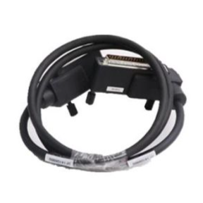
Yokogawa ∑ series driver (absolute encoder): module speed command (15B/15a) connected to driver V-REF/SG-V; Encoders A/B/Z phase (11b/11a, 12b/12a, 13b/13a) are connected to drivers PA0/* PA0, PB0/* PB0, PC0/* PC0; Servo ON (3a) connected to S-ON, driver reset (3b) connected to ALMRST, brake OFF (4a) connected to brake relay; Emergency stop (20A/20b) connected to the emergency stop switch; The SEN signal (9b/9a) is connected to the driver SEN/SEN_0V.
Sanyo P series driver (incremental encoder): module speed command (15B/15a) connected to driver VCMD/SG; Encoder A/B/Z phase (11b/11a, 12b/12a, 13b/13a) connected to drivers A+/A -, B+/B -, C+/C -; Servo ON (3a) connected to SON, driver reset (3b) connected to RST; Emergency stop (20A/20b) is connected to the emergency stop switch.
- EMERSON
- Honeywell
- CTI
- Rolls-Royce
- General Electric
- Woodward
- Yaskawa
- xYCOM
- Motorola
- Siemens
- Rockwell
- ABB
- B&R
- HIMA
- Construction site
- electricity
- Automobile market
- PLC
- DCS
- Motor drivers
- VSD
- Implications
- cement
- CO2
- CEM
- methane
- Artificial intelligence
- Titanic
- Solar energy
- Hydrogen fuel cell
- Hydrogen and fuel cells
- Hydrogen and oxygen fuel cells
- tyre
- Chemical fiber
- dynamo
- corpuscle
- Pulp and paper
- printing
- fossil
- FANUC
- Food and beverage
- Life science
- Sewage treatment
- Personal care
- electricity
- boats
- infrastructure
- Automobile industry
- metallurgy
- Nuclear power generation
- Geothermal power generation
- Water and wastewater
- Infrastructure construction
- Mine hazard
- steel
- papermaking
- Natural gas industry
- Infrastructure construction
- Power and energy
- Rubber and plastic
- Renewable energy
- pharmacy
- mining
- Plastic industry
- Schneider
- Kongsberg
- NI
- Wind energy
- International petroleum
- International new energy network
- gas
- WATLOW
- ProSoft
- SEW
- wind
- ADVANCED
- Reliance
- YOKOGAWA
- TRICONEX
- FOXBORO
- METSO
- MAN
- Advantest
- ADVANCED
- ALSTOM
- Control Wave
- AB
- AMAT
- STUDER
- KONGSBERG
- MOTOROLA
- DANAHER MOTION
- Bently
- Galil
- EATON
- MOLEX
- Triconex
- DEIF
- B&W
- ZYGO
- Aerotech
- DANFOSS
- KOLLMORGEN
- Beijer
- Endress+Hauser
- MOOG
- KB
- Moxa
- Rexroth
- YAMAHA
- Johnson
- Westinghouse
- WAGO
- TOSHIBA
- TEKTRONIX


Email:wang@kongjiangauto.com

