
YOKOGAWA FA-M3 positioning module (with analog voltage output)
Document identification: Document number IM 34M6H58-01E, document model code DOCIM. This number must be referenced for communication and additional manual purchases; The media number is the same as the document number (CD version), and the copyright belongs to Yokogawa Electric in 1998.
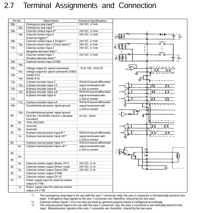
External contact outputs 3 external contact outputs (servo ON, brake OFF, driver reset), triggered by corresponding commands, polarity can be set separately, and status can be read through the application program-
The SEN signal output is only used to connect the Yokogawa Motor absolute encoder and request the transmission of absolute value data. Other drivers need to be suspended when connected-
The origin search operation writes parameters such as search direction, speed, mode (contact input detection action), Z-phase edge selection, etc., triggering the "origin search" relay. After detecting the preset external contact input or Z-phase signal, it decelerates and stops. The detection position can be used as the origin (or origin offset value) to adjust parameters in multiple cycles to achieve complex search; In the absolute encoder system, the Yokogawa method can be searched with the incremental encoder, while the Sanyo method cannot be searched
The interrupt function supports "position detection interrupt" (interrupts the CPU when the instruction/encoder position reaches the set value) and "positioning end interrupt" (interrupts the CPU when positioning is completed). Please refer to the CPU manual for handling interrupts-
After triggering the "Manual Pulse Generator Mode ON" in manual pulse generator mode, the motor is controlled by the manual pulse generator, and the ratio of pulse input to motor movement is set by the "Manual Pulse Generator Proportional Value"; Dual axis can be set to this mode simultaneously, and the shared pulse input cannot control the motor through CPU instructions in this mode; Restore position control after mode OFF
Linear interpolation operation simultaneously writes target speed, position, acceleration and deceleration parameters in both axes (with the same acceleration and deceleration time, speed ratio=movement ratio), synchronously triggers the "start operation command" relay, and after each axis completes positioning, the corresponding "positioning end" relay acts-
Starting a new positioning operation during the operation of positioning in the path, the new operation is initiated before the end of the current operation, forming a path overlap (interval in the path), without the need to stop at the middle target position, and supporting direction changes requires determining the start timing through the "remaining deceleration time" status to avoid operation conflicts
The arc interpolation operation writes parameters such as the center position, radius, starting angle, and angle movement in both axes, synchronously triggering the "start operation command" relay. The module generates the arc path through trigonometric functions to ensure that the X/Y axis parameters are consistent (starting angle, angle movement, etc.); When a single axis error occurs, the other axis continues to run, and the program needs to detect the error and stop it
Parameter settings
The module parameters are divided into entrance parameters (usually set only once after power on), startup parameters (reference for instructions such as positioning/speed control execution), origin search related startup parameters, extended instruction parameters, control mode switching parameters, and arc interpolation parameters. The core parameters are as follows:
1. Entrance parameters (key items)
Parameter Name Axis 1 Data Position Axis 2 Data Position Initial Value Range/Description
Positive limit value 001/002 201/202 134217727-134217728~134217727 pulse, set the position limit within the physical stroke
Negative limit value 003/004 203/204-134217728-134217728- (positive limit value -1) pulse
Speed limit value 005/006 205/206 131072000~131072000 (1/65536) pulse/ms, limit path generation speed
Overspeed detection value 007/008 207/208 131072000~131072000 (1/65536) pulse/ms, detecting the actual speed of the motor exceeding the limit
Super acceleration detection value 009/010 209/210 131072000~131072000 (1/65536) pulse/ms/ms, detecting actual motor acceleration exceeding the limit
Deviation error detection value 011/012 211/212 134217727 1~134217727 pulses, detecting that the deviation between the instruction position and the encoder feedback position exceeds the limit
Motor rotation direction 013 213 0 0: Positive speed command voltage corresponds to forward rotation; 1: Positive speed command voltage corresponds to reverse rotation
Encoder specification 018 218 0 0: Universal incremental type; 1: Sanyo Manchester encoding absolute formula; 2: Yokogawa Serial Absolute Formula
Speed/voltage ratio 020/021 220/221 10240 1~2000000 pps/V, calculation formula: (rated motor speed x encoder pulses/minute) ÷ rated voltage
2. Other parameters (core items)
Startup parameters: including target speed, target position, target position mode (absolute/relative), acceleration and deceleration time/mode/parameters, positioning judgment range, timeout time, interpolation mode, startup mode, position detection mode/set value, etc. There is no initial value, which needs to be written before instruction execution.
- OMRON
- ABB
- General Electric
- EMERSON
- Honeywell
- HIMA
- ALSTOM
- Rolls-Royce
- MOTOROLA
- Rockwell
- Siemens
- Woodward
- YOKOGAWA
- FOXBORO
- KOLLMORGEN
- MOOG
- KB
- YAMAHA
- BENDER
- TEKTRONIX
- Westinghouse
- AMAT
- AB
- XYCOM
- Yaskawa
- B&R
- Schneider
- KONGSBERG
- NI
- WATLOW
- ProSoft
- SEW
- ADVANCED
- Reliance
- TRICONEX
- METSO
- MAN
- Advantest
- STUDER
- DANAHER MOTION
- Bently
- Galil
- EATON
- MOLEX
- DEIF
- B&W
- ZYGO
- Aerotech
- DANFOSS
- Beijer
- Moxa
- Rexroth
- Johnson
- WAGO
- TOSHIBA
- BMCM
- SMC
- HITACHI
- HIRSCHMANN
- Application field
- XP POWER
- CTI
- TRICON
- STOBER
- Thinklogical
- Horner Automation
- Meggitt
- Fanuc
- Baldor
- SHINKAWA
- Other Brands
- UniOP
- KUKA
- Iba
- Beckhoff
-
 OMRON CJ1W-MD261 Mixed I/O Module
 -
 Omron NJ301-1100 PLC CPU eCat EIP Specs
 -
 Omron F500-C15-ETN Vision System PLC Module
 -
 Modicon M241-24IO TM/T2UK PLC with Ethernet
 -
 SIXNET YS-800-001 RTU PLC Module
 -
 BEMAC UST-202-D Interface Board 1307D V08B2
 -
 Yaskawa JANCD-MMOIC-02 Drive Circuit Board
 -
 ABB 3BSE005028R1 SDCS-COM-1 Comm Board
 -
 Omron 3G3MX2-A4110 A4150 Inverter Drives Specs
 -
 KEYENCE CA-E100 PLC Module
 -
 GE IC693ALG223-GB Analog Input Module Specs
 -
 ABB BAILEY IMMFP01 Multi Function Processor System
 -
 SIEMENS 6FC5372 0AA00 0AA1 NCU 7202 Controller
 -
Modicon TM241CE4 40I O Transistor Programmable Controller
-
 SIEMENS 6ES7 315 2EH13 0AB0 CPU 3152 PN DP
 -
 NORIS A1 91 PCB Card Rack Module System
 -
 SIEMENS 6ES7 313 5BE01 0AB0 Compact CPU
 -
 SCHNEIDER ELECTRIC S144B MICROLOGIC 60A Trip Unit
 -
 CNI PLC269 v3 Control Module Board Rev H
 -
ABB BAILEY IIMCP02 Processor Module
-
 OMRON NT20S ST121 EV3 Operator Interface Terminal
 -
 OMRON NS-CA001 Video Input Unit
 -
 GE Fanuc IC695CHS012 RX3i Backplane
 -
 Allen Bradley 2711E-K14C6 PanelView 1400e Terminal
 -
 Siemens Sinamics CCB 10000432.71 Power Cell
 -
 Siemens 6SL3210-1SE21-8UA0 Power Module PM340
 -
 Yaskawa CIMR-F7A20P4 AC Drive
 -
 Beckhoff EP1918-0002 EtherCAT Box I/O Module
 -
 OMRON CQM1-TC001 Temperature Control Module
 -
 GE Fanuc SGHA36AT0400 Industrial Contactor
 -
 OMRON NJ501-1500 PLC Machine Automation Controller
 -
 Mitsubishi MAZAK QX084 Power Supply MELDAS 500 CNC
 -
 B&R 0AC808.9 PLC Automation Module
 -
 OMRON CP1H-XA40DT1-D PLC Module
 -
 G&W Electric PLC15 5111 011 15kV Capnut Assembly
 -
 GE DS200SLCCG3AGH PCB Circuit Board
 -
 Siemens SINUMERIK 6FC3981-4FD PLC Extension
 -
 OMRON F300-DC I/O Image Processing Unit
 -
 FANUC A06B-0314-B002 AC Servo Motor
 -
 GC-S84 Programmable Controller Logic Module
 -
 PASABAN MONTELEC MTC3001-DC Drive Control PLC
 -
 Allen Bradley 100E460EJ11 Auxiliary Contactor
 -
 Bosch Rexroth 1070075337-101 Card Parameters
 -
 HMS Anybus AB7646-F Gateway Specifications
 -
 Bosch 062633-303401 CNC Servo PLC Card
 -
 TI 500-5023 Series PLC Power Supply
 -
 Siemens C98043-A7002-L1-12 Circuit Board
 -
 Omron E5CC-RX3A5M-000 Controller
 -
 CN-8032-L Profinet Network Adapter Module
 -
 Siemens 3TK2804-0BB4 Safety Relay Details
 -
 Toledo TTLM-2-1M I/O Load Module
 -
 NORIS A1-91 PLC Rack Board Specifications
 -
 Mitsubishi A3ACPUR21 MELSEC PLC CPU Module
 -
 Beckhoff EP7041‑3002 EtherCAT Box Digital Input Module
 -
 REER EOS2E 1053 EOS2R 1053 Safety Light Curtain
 -
 Mitsubishi Q80BD-J71BR11 MELSECNET/H Interface Board
 -
 Omron 3G3IV-B4220-EV2 VFD 400V 22kW
 -
 Allen-Bradley 96844671 1785-LT3 PLC-5/12 Processor Module
 -
 Pasaban MTC3001-DC Drive Control PLC Module
 -
 Omron CJ1M-CPU11 V4.0 PLC CPU Module
 -
 ABB CM579-PNIO B3 Communication Module
 -
 B&R X20 AI 4221 Analog Module
 -
 Siemens 6SY7000-0AC80 PLC Module
 -
 GE 531X300CCHAFM5 Control Card
 -
 AB 810-A15C Inverse Time Relay
 -
 WITTENSTEIN LP120X-MF2-20 Planetary Gear
 -
 Mitsubishi Kakoki E-01B-4130 PLC I/O Modules
 -
 ABB DSQC643 Safety Control Board
 -
 Siemens G26004-A2105-P100-2 PCB
 -
 OMRON F350-C10E Image Processing Unit
 -
 FUJI UG430H-TS1 HMI Touch Panel
 -
 Westronics CB100188-01 Rev F Board
 -
 Siemens 7MH4900-3AA01 Weighing Module
 -
 Gilbert & Nash Tracker 2000 Control Cabinet
 -
 OMRON CJ1M-CPU22 CPU Unit
 -
 OMRON F3SJ-E0625P25 Light Curtain
 -
 Siemens 3VA2340-5HL32-0AA0 Breaker
 -
 Mitsubishi Melsec A61P A2NCPU PLC System
 -
 Aeco 158-02 DSP-02 PCB Card
 -
 FUJI NP1PS-32R CPU Module
 -
 Siemens 6SL3040-1MA01-0AA0 Control Unit CU320-2 PN
 -
 Fuji RYE.75D PLC Driver AC Drive
 -
 Electro Cam PS-6144-24-P16M09-L-MB Programmable Limit Switch
 -
 Siemens C98043-A7001-L2-4 CUD1 Control Board
 -
 Pilz 312070 PSSu H PLC1 FS SN SD Safety Module
 -
 Siemens Plc42q4200atsn Circuit Breaker Fuse Box
 -
 GE Fanuc IC695ALG708-AB Analog Output Module Rx3i
 -
 Siemens 6SE7036-5GK84-1JC2 IGD8 Gate Driver Board
 -
 Charmilles 813078 852029 PLC PCB Robocut 2 CNC EDM
 -
 Siemens 6SL3130-1TE24-0AA0 Smart Line Module
 -
 Pasaban MTC3001-DC Drive Control PLC Module
 -
 Modicon AS-P890-000 Remote I/O Processor Power Supply
 -
 Siemens PXC100-PE96.A PXC Modular Controller
 -
 TOYO KEIKI P:CARD5 AVH-R YH-212 Industrial Control Card
 -
 Omron NS5-SQ00B-V2 HMI Touch Screen 5.7 Inch
 -
 Sciemetric SigPOD 1202-0H00 Data Acquisition Module
 -
 GE Fanuc IC693CPU331W CPU Module Series 90-30
 -
 Square D 8903SVO11V02 Lighting Contactor 200A
 -
 Beckhoff C9900-P224 Power Supply Unit 24V 10A
 -
 HSD PE323 PLC I/O Module
 -
 Pillar AB6406-11A Power Control Board
 -
 GE Fanuc IC693CPU331W CPU Module
 -
 FANUC A61L-0001-0072 LCD Monitor
 -
 AB 20D-D-011-A-0-EYNANANE Drive
 -
 AB 1785-L20B PLC-5/20 Processor
 -
 Siemens SIREC P/PA Recorder 7ND3021
 -
 Siemens D2E160-AH01-17 Fan Blower
 -
 Eaton 101073735-001 LEG Module
 -
 AB 1404-M605B-ENT Powermonitor 3000
 -
 OMRON CJ1W-MAD42 Analog I/O
 -
 Omron CJ1M-CPU13 V3.0 PLC CPU Module
 -
 Pe323 HSD PLC Module Industrial Controller
 -
 Pasaban MTC3001-DC Drive Control PLC Module
 -
 Mitsubishi R02CPU PLC Module MELSEC iQ-R
 -
 B&R X20DC2395 Digital Output Module 32 Ch
 -
 Hoffman A30N24ALP Enclosure with PLC Addons
 -
 Rieter PLC with RMC 24/5V 10 RMC188-1 RMC RIO-1
 -
 Allen-Bradley 1790D-TN4V0 CompactBlock LDX Base Block 4 AI
 -
 National Instruments NI 9242 Analog Input Module 4-Channel
 -
 ABB AO820 3BSE008546R1 Analog Output Module
 -
 Moeller XVC-101-C192K-K82 PLC
 -
 AB 440F-C4000P MatGuard Controller
 -
 AB 1692-ZRCLSS Protection Module
 -
 Schneider S48896 PLC Module
 -
 FANUC A02B-0303-C205 I/O Module
 -
 AB 1785-LT4 PLC-5/10 Processor
 -
 AB 1746-NO8V SLC 500 Analog Output
 -
 OMRON CQM1-TC001 Temperature Unit


