
Omron C200HX/HG/HE PLC Installation Guide
Crimping terminals: All wiring must use M3.5 crimping terminals, and direct connection of bare wires is strictly prohibited.
Stripping length: The stripping length of the terminal is about 7mm.
Tightening torque: The tightening torque for terminal screws is 0.8N · m.
4.2.2 Input Unit Wiring
The ON voltage of the DC input unit (such as C200H-ID211) is 10.2VDC min, the OFF voltage is 3.0VDC max, and the response time is 1.5ms. When using two-wire sensors (such as photoelectric switches and proximity switches), attention should be paid to the possibility of input misoperation caused by leakage current. If the leakage current is greater than 1.3mA, a discharge resistor should be connected in parallel.
4.2.3 Output Unit Wiring
Relay output: The contact life of relay output units (such as C200H-OC221) depends on the load current and temperature. At 55 ℃, the contact life is only one-fifth of that at room temperature. To extend the lifespan, a surge absorber (RC circuit) should be connected in parallel to absorb the reverse electromotive force of inductive loads.
Transistor output: The transistor output unit (such as C200H-OD411) has residual voltage (maximum 1.4V) and leakage current (maximum 0.1mA). When connecting TTL circuits, an external pull-up resistor is required.
Short circuit protection: Output units with short circuit protection function (such as C200H-OD214) will cut off the output and light up the alarm indicator when the output is overcurrent or overheated. After troubleshooting, the output can only be restored by pressing the reset button or powering on again.
4.2.4 Anti interference measures
The input and output signal lines should be wired separately from the power lines to avoid sharing pipes or slots. If unavoidable, shielded cables should be used and the shielding layer should be connected to the GR terminal.
Parallel surge suppressors or diodes are connected at both ends of inductive loads (such as relay coils and solenoid valves) to absorb the reverse electromotive force generated during shutdown.
For loads that may generate high surge currents (such as incandescent lamps), current limiting resistors can be connected in series or small current bypass resistors can be connected in parallel at the output end to reduce surge impact.
Fault diagnosis and maintenance
5.1 Common troubleshooting
5.1.1 The power indicator light is not on
Possible reasons include: incorrect voltage selection, external short circuit of 24V output terminal, blown internal fuse, or power unit failure. Check the wiring and confirm the input voltage. If the fuse is blown, replace the power unit.
5.1.2 RUN indicator light does not light up
Possible reasons: program error (such as missing END instruction), CPU unit failure, duplicate unit numbers for special I/O units, or failure to turn on the slave power. Check the program and correct errors, confirm that the unit number is set uniquely.
5.1.3 Input point faults
The indicator light is not on and there is no input: check the external input power supply, input voltage, terminal screw tightness, and connector contact.
Input point always ON: Check whether the input circuit, input device, and wiring are open circuited. If the input point address is used as an output instruction in the program, it will also cause the input point to fail to close.
5.1.4 Output point fault
No output: Check the load power supply, output voltage, terminal tightness, and whether the fuse is blown.
Output point always ON: Check if the output circuit and program output instructions overlap. For transistor output, it is necessary to check whether leakage current causes misoperation.
Abnormal output point action: Check the load power supply voltage, program logic, and take anti noise measures.
5.2 Regular maintenance
5.2.1 Fuse replacement
Some output units (such as C200H-OD411, C200H-OA221) are equipped with fuse indicators. The fuse specification is 5 × 20mm, and UL/CSA certified equivalent fuses must be used for replacement. The fuse of the high-density I/O unit cannot be replaced by the user and needs to be repaired by contacting the supplier.
5.2.2 Relay replacement
The relay of the relay output unit (such as G6B-1174P-FD-US-M 24VDC) can be replaced with a dedicated puller. The puller is located at the rear of the unit casing. When replacing, be sure to check the pin arrangement to avoid forcefully inserting and causing the pins to bend.
5.2.3 Battery replacement
The CPU unit uses C200H-BAT09 batteries, with a normal lifespan of 5 years (25 ℃). When the ERR indicator light flashes and the programming console displays "BATT FAIL", the battery needs to be replaced within one week. Replacement steps:
Disconnect the PLC power supply, or keep the power on for at least one minute before cutting off the power.
Remove the CPU unit from the backplane.
Open the battery compartment cover on the back of the CPU unit.
Pull out the old battery connector and insert the new battery.
The entire process must be completed within 5 minutes to prevent data loss.
5.3 Power supply unit with replacement notification function (C200HW-PA204C)
The power unit is equipped with a built-in electrolytic capacitor life monitoring function. During normal operation, the seven segment digital display shows the remaining lifespan (such as "FUL", "HLF", "1.5", etc.). When the remaining lifespan is less than 6 months, the display flashes alternately with "0.0" and "A02", and the alarm output (open collector) changes from ON to OFF. At this point, the power unit should be replaced within 6 months.
- ABB
- General Electric
- EMERSON
- Honeywell
- HIMA
- ALSTOM
- Rolls-Royce
- MOTOROLA
- Rockwell
- Siemens
- Woodward
- YOKOGAWA
- FOXBORO
- KOLLMORGEN
- MOOG
- KB
- YAMAHA
- BENDER
- TEKTRONIX
- Westinghouse
- AMAT
- AB
- XYCOM
- Yaskawa
- B&R
- Schneider
- Kongsberg
- NI
- WATLOW
- ProSoft
- SEW
- ADVANCED
- Reliance
- TRICONEX
- METSO
- MAN
- Advantest
- STUDER
- KONGSBERG
- DANAHER MOTION
- Bently
- Galil
- EATON
- MOLEX
- DEIF
- B&W
- ZYGO
- Aerotech
- DANFOSS
- Beijer
- Moxa
- Rexroth
- Johnson
- WAGO
- TOSHIBA
- BMCM
- SMC
- HITACHI
- HIRSCHMANN
- Application field
- XP POWER
- CTI
- TRICON
- STOBER
- Thinklogical
- Horner Automation
- Meggitt
- Fanuc
- Baldor
- SHINKAWA
- Other Brands
- UniOP
- KUKA
-
 GE IM 3100 D 1007722 Control Module
 -
 GE IM0146B Industrial Circuit Board
 -
 GE IM0059E0-10070 Interface Board
 -
 GE IM0094C Industrial Control Board
 -
 GE IC200PNS002-AB VersaMax PROFINET Scanner
 -
 GE F650BFBF1G0HI Feeder Protection Relay
 -
 GE TPR5616NRHC Protection Relay
 -
 GE D6P3KH Digital Protection Relay
 -
 GE F650BABF2G0HIS Feeder Protection Relay
 -
 GE F650BADF2G1HIR Feeder Protection Relay
 -
GE F650BABF2G1HI6 Digital Bay Controller
-
 GE Multilin 745-W2-P1-G1-H-I-A-R-E Transformer Protection Relay
 -
 GE 100BASE-T Industrial Ethernet Interface
 -
 GE Multilin 350-E-P1-S1-H-S-E-C-N-2E-D-H Feeder Protection System
 -
 GE F650MXCF1G1HI6 Bay Controller
 -
 GE MM300-GEHD2CAB Motor Management Relay
 -
 GE MMS35-621-1-00 Motor Management System
 -
 GE 100BASE-T Ethernet Communication Module
 -
 GE F650MFCF1G1HI6 Feeder Protection Relay
 -
 GE CK13BA300 Control Module
 -
 GE W2-P1-G1-H Industrial Control Unit
 -
 GE PIB315B Power Interface Board
 -
 GE 343L695VAGIRHC Multi-Function Relay
 -
 GE Multilin B90N05HKHF8NH6 Bus Differential Protection
 -
 GE ZX3SC0204N-930 Intelligent Control Module
 -
 GE PIB504 Process Interface Board
 -
 GE D20MX Remote Terminal Unit
 -
 GE T60UJ3HKHF8NH6 Transformer Protection Relay
 -
 GE ZG3SA02041-58S600X Motor Protection Relay
 -
 GE ZG3SA02041-58S Motor Protection Relay
 -
 ABB DSDX 452 L Remote Input Output Module
 -
 ABB RDCU-02C Drive Control Unit
 -
 ABB COMMANDER 350 Process Controller
 -
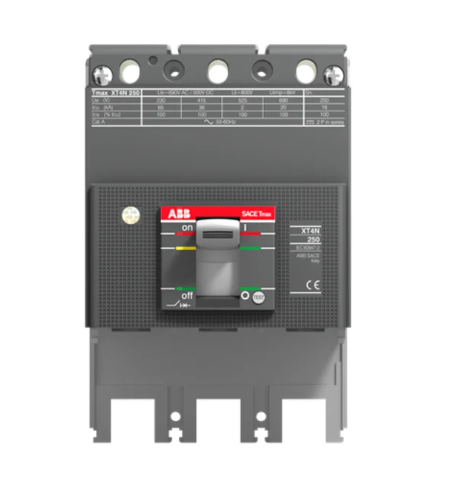 ABB Tmax XT4S 250 Molded Case Circuit Breaker
 -
 DEIF MALLING 8027.90 Industrial Control Unit
 -
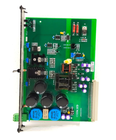
 DEIF DCP2-2410 Power Supply Module
 -
 DEIF FAS-2N Synchronizer
 -
 DEIF MALLING 827.54 Processor Module
 -
 DEIF DU-2/MKIII Display Unit
 -
 DEIF DRW-2 Reverse Power Relay
 -
 DEIF 827.4 Power Management Module
 -
 DEIF 1044220060F Mains Measurement Module
 -
 DEIF 1044220190G Remote Display Module
 -
 DEIF 1044220140C AGC 200 Display Module
 -
 DEIF BRW-1-NB Remote Display Unit
 -
 DEIF MALLING 827.52 Industrial Control Unit for Automation Systems
 -
 DEIF BRW-2 Industrial Relay Module for Control Systems
 -
 DEIF 1044220080D Power System Control Module Industrial Automation
 -
 DEIF 1044220100F Controller Module for Generator Control Systems
 -
 DEIF DU-300 Voltage Monitoring Relay Industrial Protection Unit
 -
 DEIF 1044220060F I/O Extension Module
 -
 DEIF 1044220150C Interface Module
 -
 DEIF GCU 100 Engine Control Unit
 -
 DEIF XDI144-DUAL Marine Indicator
 -
 DEIF 827.41 Multi-line 2 Processor Module
 -
DEIF AGC 146 Automatic Genset Controller
-
 DEIF 1044220080E MDR-2 Display Module
 -
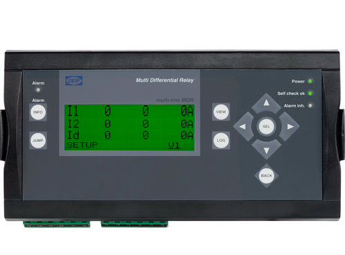 DEIF MDR-2 Multifunctional Digital Relay
 -
 DEIF 1044220070E PPU-3 Display Module
 -
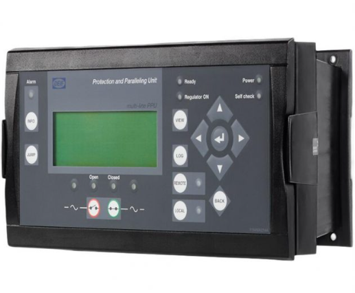 DEIF PPU-3 Paralleling and Protection Unit
 -
 Siemens 6SL3210-1SE21-8UA0 PM340 Power Module SINAMICS Drive System
 -
 Yaskawa JANCD-XCP01C-1 Servo Control Board with JANCD-XIF04-1 Network Interface
 -
 BRISTOL 396879-01-2 C Wave Micro PLC CPU with Ethernet Industrial Controller
 -
 OMRON SGDH-10DE-OY Servo Drive High Precision Industrial Motion Control Amplifier
 -
 OMRON FQM1-MMA22 PLC High Performance Motion Controller Module
 -
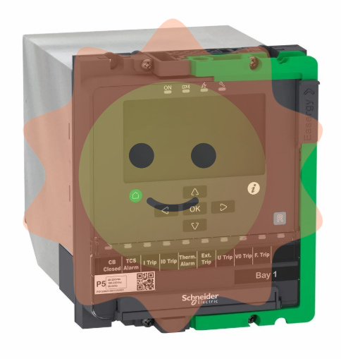 Schneider PowerLogic P5F30 Protection Relay
 -
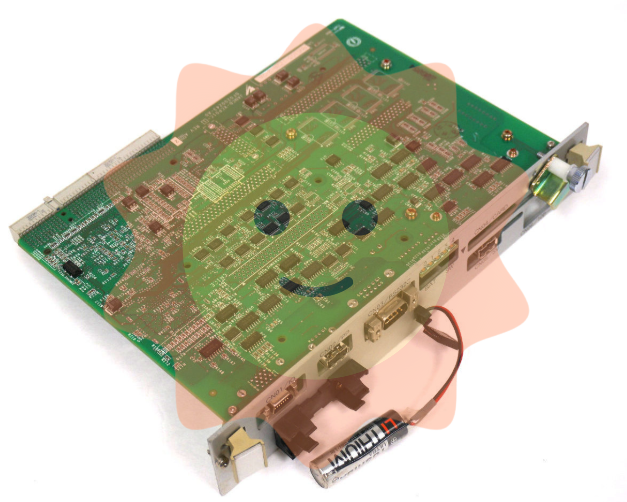
 ABB DSPC53 57310256BA/2 Processor PCB
 -
 ABB Jokab 2TLJ020070R1700 Eden Safety Sensor
 -
 Lenze HMI EL 105C 3351-1 2 Control Panel
 -
 Pilz PSEN op4-s-30-060/1 Safety Light Curtain Specs
 -
 Vacon NXI01055A2T0CSSA1A3AK00C6 AC Drive
 -
 Square D PowerLogic CM4250 Circuit Monitor
 -
 Siemens CPU314C-2PTP Simatic S7-300 PLC
 -
 Eaton E84BAN Communication Interface Module
 -
 Prosoft MVI56 PDP-MV1 Profibus Master Module
 -
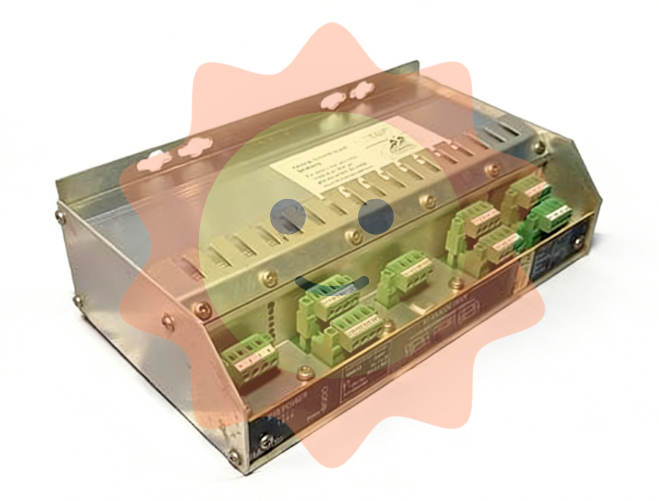 Kongsberg MEI 8100276 Multi I/O Interface Module Marine Control System
 -
 Kongsberg MD 22 TN Display Module Marine Control Display Unit
 -
 Kongsberg MSI 8100222 Multi Signal Interface Module Marine Control System
 -
 Kongsberg RDO-16 8100155 Digital Output Module Marine Control System
 -
 Kongsberg RAO-8 8100153 Analog Output Module Marine Control System
 -
 Kongsberg C2 8100182 Controller Module
 -
 Kongsberg dPSC 8100183 Digital Process Controller
 -
 Kongsberg SPBUS-HUB 600309 Process Bus Hub
 -
 Kongsberg Simrad BP413R 37960580 A PCB Card
 -
 Kongsberg RAi-10tc 8100161 Remote Analog Input
 -
 Kongsberg NL-290 KM-F Navigation Light Panel
 -
 Kongsberg RAI-16xe Remote Analog Input Module
 -
 Kongsberg dPSC 8100183 Dynamic Positioning Control Panel
 -
 Kongsberg NK-210 NU02 Control Panel
 -
 Kongsberg RAIC400 Remote Analog I/O Controller
 -
 Kongsberg Simrad SJS-01/02 Sonar Sensor Marine Detection System
 -
 Kongsberg RAo-8 Analog Output Module Marine Automation Control Module
 -
 Kongsberg MP 530 Operator Panel Unit Marine Control Interface System
 -
 Kongsberg PSO-P 8100334 Power Supply Unit Marine Automation Power Module
 -
 Kongsberg dPSC 8100183 Dynamic Positioning Controller Marine Control System
 -
 Kongsberg MP 8200 Processor Module
 -
 Kongsberg MP 8300 Multi Processor Board
 -
 Kongsberg MCU8625 Marine Control Unit
 -
 Kongsberg MP 5810 Multi Processor Board
 -
 Kongsberg DSU 001 Dual Slot Unit
 -
 Kongsberg RCU 510 Remote Control Unit
 -
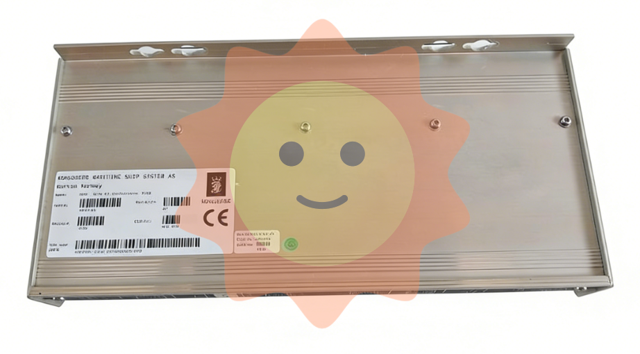
 Kongsberg BS610 Battery Supply Unit
 -
 Kongsberg M410-10 Alarm Monitoring Panel
 -
 Kongsberg HMS 100 Hull Monitoring System
 -
 Honeywell TCF901 Gas Detector
 -
 Honeywell 9938R Relay Output Module Industrial Control Switching Module
 -
 Honeywell XL1000C1000 Building Automation Controller HVAC Control System
 -
 Honeywell S0762970 I/O Interface Module Industrial Automation Signal Module
 -
 Honeywell RM7850 Burner Control Module Industrial Flame Safeguard Controller
 -
 Honeywell IPC1100 Industrial Panel Computer Automation Control HMI System
 -
 Honeywell TDID72 Digital Input Module
 -
 Honeywell TCNT01 Control Processor Interface
 -
 Honeywell C300 Controller Process Automation
 -
 Honeywell 51304337-250 Redundancy Cable Assembly
 -
 Honeywell PAL 2053 Programmable Array Logic Board
 -
 Honeywell IOC2053 Input Output Card
 -
 Honeywell PAIH03 Analog Input Module
 -
 Honeywell IPC 621 Industrial Computer
 -
 Honeywell 05701-A-0301 Process Control Card
 -
 Honeywell 10302/2/1 Power Supply Module
 -
 Honeywell SPXCDALMTX4 Gas Detector Module Industrial Safety Monitoring Device
 -
 Honeywell PHAI01 Analog Input Module Industrial Automation Input Module
 -
 Honeywell 63AP3070 Pressure Transmitter Industrial Measurement Module
 -
 Honeywell P522AC Analog Controller Module Industrial Control System Component
 -
 Honeywell K2LCN-4 ControlNet Interface Module Industrial Communication Module
 -
 Honeywell M6184D1035 Proportioning Actuator
 -
 Honeywell PCF901 Pulse Control Interface Module
 -
 Honeywell 05701-A-0302 Gas Detection Control Card


