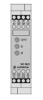
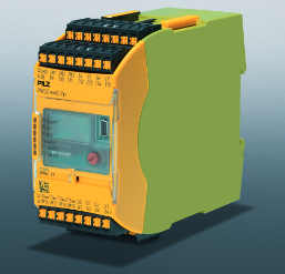
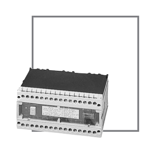
Pilz 774595 PZE X5 Safety Contact Expansion Module
The Pilz 774595 PZE X5 is a safety contact expansion module, an add-on device without delay-on de-energization used to expand the number of safety contacts available from a base safety relay. When connected to a Pilz PNOZ series safety relay or emergency stop relay, the PZE X5 replicates the safety output state, providing five additional normally open (N/O) safety contacts. This enables a single base safety relay to control multiple loads or to distribute safety signals to multiple control zones without compromising the safety integrity of the system.
Input and Output Configuration
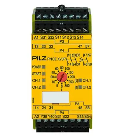
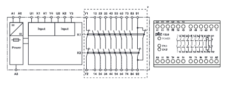
The PZE X5 features five normally open safety outputs, designated 13-14, 23-24, 33-34, 43-44, and 53-54. All five outputs are forced-guided safety contacts, ensuring that welding or mechanical sticking cannot prevent the contacts from opening when commanded. The input circuit is designed for one-channel or two-channel wiring, with or without detection of shorts across contacts. When wired in two-channel mode, the module monitors both input channels for discrepancies, providing higher diagnostic coverage appropriate for Category 3 or Category 4 safety circuits per EN ISO 13849-1. The power supply voltage is 24 V DC, with an internal indicator LED labeled "POWER" to confirm supply presence. When the input circuit is closed, all five safety contacts close redundantly, and the channel LEDs (CH.1 and CH.2) illuminate to indicate correct input state.
Mechanical and Mounting Details
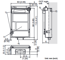
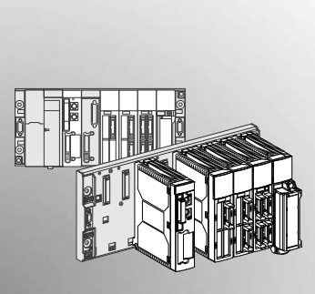
The PZE X5 has a width of 45 mm, fitting standard DIN rail mounting systems. The housing is constructed from insulating material with a protection rating suitable for installation within a control cabinet. The module is mounted onto a 35 mm DIN rail using the notched rear of the unit, and should be secured with a fixing element such as a retaining bracket or end angle, particularly when installed vertically. Dimensions follow the standard Pilz safety relay form factor, allowing consistent panel layouts and simplified spare parts stocking. Integral screw terminals provide permanent and secure connections, eliminating the need for separate terminal blocks for low-current signal wiring.
Operation and Function Description
The PZE X5 is an add-on device without delay-on de-energization, meaning it follows the state of the base unit without introducing any intentional time delay. When the operating voltage is supplied, the "POWER" LED lights. When the input circuit is closed (for example, when safety contacts on the base unit close), the functional procedure initiates, the safety contacts 13-14 through 53-54 close, and the LEDs "CH.1" and "CH.2" illuminate. When the input circuit is opened (safety contacts on the base unit open), the safety contacts open redundantly and the channel LEDs go out. The module does not contain its own logic or self-monitoring; its safe state depends entirely on the correct operation of the driving base unit. Therefore, the PZE X5 must only be used with safety-rated base units that provide the appropriate input drive capability.
Wiring and Installation Guidelines
The unit should be installed in a control cabinet with a protection type of at least IP54. Wiring must follow the detailed terminal assignment diagram, with outputs 13-14, 23-24, 33-34, 43-44, and 53-54 identified as safety contacts. To prevent contact welding due to fault currents, a fuse should be connected before the output contacts as specified in the technical details. Wire should be copper and capable of withstanding 60/75°C. Sufficient fuse protection must be provided on all output contacts when driving capacitive or inductive loads. The power supply must comply with regulations for extra low voltages with protective electrical separation (SELV, PELV) in accordance with VDE 0100, Part 410. The wiring and EMC requirements of EN 60204-1 must be observed. Maximum allowable cable length in the input circuit must be calculated based on cable resistance and overall ohmic limits.

Applications and Safety Ratings
The PZE X5 is suitable for use in safety circuits up to Category 4, Performance Level e, provided it is driven by a base unit that achieves that category and is wired in accordance with the relevant standards. Typical applications include expanding the number of contacts available from an emergency stop relay to control multiple motor contactors, light curtains, or safety gates. The module can also be used to split a safety signal to multiple zones that must all be de-energized simultaneously, such as in a large machine with several guarded access points. When the base unit initiates a safety stop, the PZE X5 drops out all five safety contacts within the specified response time, removing power from connected loads.
Safety Precautions
Low currents should not be switched using contacts that have been used previously with high currents, as the contact surface condition can affect reliability. The module contains no internal fault detection beyond monitoring of the input circuit; all diagnostic functions reside in the base unit. When replacing a PZE X5, power must be disconnected before removal, and the wiring must be transferred exactly to the same terminals on the replacement unit. After installation, a functional test should be performed to verify that all five safety contacts open when the input circuit is opened.