
Woodward PG-PL Hydraulic Governor: Reliable and Accurate Engine and Turbine Speed Control Solution
Woodward PG-PL Hydraulic Governor: Reliable and Accurate Engine and Turbine Speed Control Solution
Introduction
Accurate and stable control of the rotational speed of prime movers (engines, steam turbines, gas turbines, etc.) is the cornerstone of ensuring equipment efficiency, safety, and reliability in key fields such as industrial drive, power generation, ship propulsion, and oil and gas pipelines. The Woodward PG-PL governor is a proven hydraulic Isochronous governor that integrates a pneumatic speed setting mechanism. With its sturdy structure, responsive nature, and easy maintenance, it performs well in various diesel, gas, and steam turbine applications. This article provides a systematic explanation of the principle, installation, commissioning, maintenance, and components of the PG-PL speed controller based on Manual 36694P.
Product Overview and Core Features
1. Basic composition
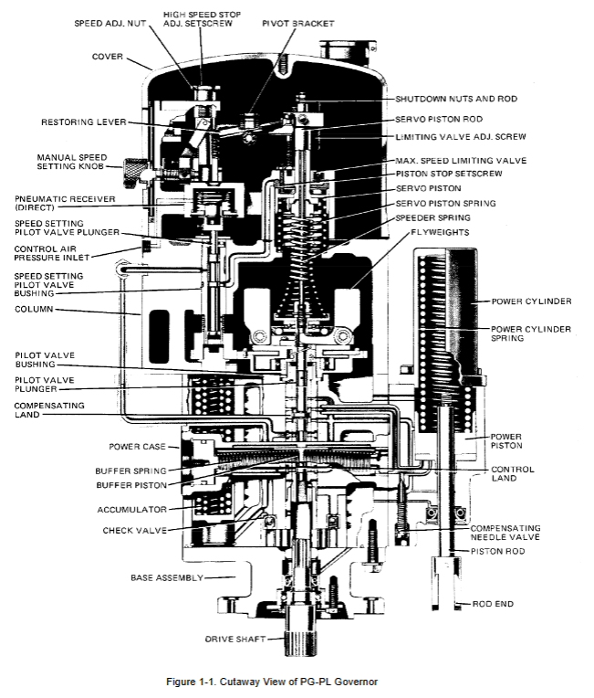
The PG-PL governor is a variant of the basic PG (pressure compensated) governor, and its core system includes:
Hydraulic pump, accumulator, and relief valve: Provide and maintain a working oil pressure of approximately 100 psi (690 kPa) (which can be increased as needed).
Centrifugal flying hammer pilot valve assembly: sensing speed changes and controlling oil flow direction.
Power cylinder (servo motor): outputs linear (maximum 25mm) or rotational (maximum 30 °) displacement, directly driving the fuel rack or steam valve.
Buffer compensation system: Ensure stable speed regulation process and avoid drifting.
Pneumatic speed setting mechanism: Remote speed setting is achieved through a pressure signal of 3-100 psi (21-690 kPa), supporting two modes: positive action (pressure rise, speed rise) and negative action (pressure drop, speed rise).
2. Main technical parameters
Standard working oil pressure: 100 psi (690 kPa), can be increased to 200 psi (1379 kPa) to increase output capacity.
The rated power capacity of the power cylinder is available from 12 ft lb (16 J) to 200 ft lb (271 J).
Speed setting range: usually 250-1000 rpm, with a maximum adjustable range of 200-1600 rpm.
Pneumatic signal range: typically 3-15 psi (21-103 kPa) or 10-60 psi (69-414 kPa), with a high/low pressure ratio between 2.5:1 and 10:1.
Working temperature: ambient temperature -20 to+200 ° F (-29 to+93 ° C); recommended continuous operating oil temperature is 140-200 ° F (60-93 ° C).
Key steps for installation and debugging
1. Key points of mechanical installation
The installation base should be flat and use shims to ensure that the drive shaft is aligned.
The linkage mechanism must have no jamming or virtual position. When in the "closed" position, the fuel/steam valve should be precisely closed; Before reaching the maximum position, the fuel control should be fully open.
Important safety warning: Before adjusting the governor on running equipment, it is necessary to confirm that the independent overspeed shutdown device is functioning properly.
2. Selection and filling of hydraulic oil
Hydraulic oil has both lubrication and transmission functions, and selection is crucial:
Viscosity range: At operating temperature, the viscosity should be between 50-3000 SUS, with an ideal range of 100-300 SUS.
Oil type: Mineral or synthetic oils that comply with API "S" or "C" series (SA to SF, CA to CD), or oils that comply with specific US military standards (such as MIL-L-2104).
Oil level check: When the engine is idling, the oil level should be between the markings on the oil level gauge. The oil level shall not be higher than the joint surface between the shell and the column to avoid foam generated by the flying hammer.
3. Core adjustment: compensating needle valve
This is the most critical adjustment that affects stability:
The engine is running at idle speed, and the compensating needle valve is opened several times to induce travel (to discharge air from the hydraulic circuit).
Gradually close the needle valve until the traveling block is just eliminated. The needle valve opening is usually between 1/16 and 2 turns. Do not completely close.
Manually interfere with the speed setting, and check that the recovery process should only have slight overshoot or undershoot.
If necessary, loosen the exhaust screw on the housing to exhaust until the bubbles disappear and tighten.
4. Speed setting adjustment (pneumatic mechanism)
The steps for setting positive and negative effects are different, and the manual provides detailed procedures. The core is:
Use the manual speed setting knob and the high-speed stop adjustment screw as a reference.
Match the pneumatic signal range and speed range by adjusting the pivot bracket.
Set the minimum speed adjustment screw and stop nut to define the behavior when the air source fails (to idle or stop).
Adjust the maximum speed limit valve and open it before overspeeding by about 10 rpm to provide additional protection.
Deep analysis of working principle
PG-PL governor is a typical hydraulic mechanical constant speed governor, whose core is force balance and hydraulic feedback.
Speed sensing and comparison: The drive shaft drives the flying hammer to rotate, generating centrifugal force that counteracts the downward force of the speed regulating spring. When the two are balanced, the control console shoulder of the pilot valve plunger just covers the regulating oil port, and the power cylinder piston remains stationary.
Speed deviation correction:
Load increase (speed decrease): The centrifugal force of the flying hammer decreases, the flying hammer retracts, and the pilot valve plunger moves downward. The pressure oil enters the buffer system and the lower part of the power cylinder through the opened oil port, pushing the power piston upward to increase fuel. At the same time, the buffer piston moves and compresses the spring, generating differential oil pressure that acts on the compensating shoulder of the pilot valve, assisting it in quickly returning to the center.
Load reduction (speed increase): The process is reversed, and the power piston descends under the action of the power spring to reduce fuel.
Pneumatic speed setting: The air pressure signal is applied to the bellows (or old-fashioned diaphragm), and the position of the speed setting pilot valve is changed through the connecting rod, thereby controlling the oil flow entering the upper part of the speed setting servo piston, changing the preload force of the speed regulating spring, and ultimately achieving the adjustment of the speed setting point. Restore the lever to provide mechanical feedback, allowing the pilot valve to return to the center when the position is reached.
Buffer compensation system: It is the key to system stability. The compensating needle valve controls the balance speed of oil pressure on both sides of the buffer piston, and its opening directly affects the system damping and response speed.
Maintenance, fault diagnosis, and disassembly and assembly
1. Common troubleshooting
Unstable speed (traveling block): First, check whether the load fluctuates, whether each cylinder of the engine is working normally, and whether the linkage mechanism is stuck. Then check the compensation needle valve setting, oil viscosity and cleanliness, and whether the governor drive gear has excessive clearance or tightness.
Governor has no response or slow action: Check whether the working oil pressure is normal (through the pressure tap on the housing), whether the oil level is sufficient, and whether the oil is contaminated or deteriorated.
Important reminder: Dirty oil is the root cause of most governor failures. It is crucial to regularly change the oil and use clean containers.
2. Key points for disassembly, assembly, and maintenance
Disassembly sequence: Follow the index number sequence in the exploded diagram (Figure 5-1, 5-2) in the manual.
Cleaning: Use a suitable cleaning agent (such as Federal Standard P-D-680) for ultrasonic or agitation cleaning, and blow dry with dry compressed air.
Inspection: Focus on checking the wear of the flying hammer feet, the smoothness of the rotation of all bearings, the fit clearance of the piston/valve core, and whether there are scratches on the sealing surface.
Assembly: carried out in a dust-free environment. When assembling the flying hammer head pilot valve liner assembly, it is necessary to center the pilot valve plunger to ensure that the length of the console shoulder exposed by the control oil port is equal when the flying hammer is in the inner and outer limit positions.
Power cylinder installation: The tightening bolt torque must be 45 lb ft (61 N · m).
Optional auxiliary functions
Oil cooler: Required when the operating temperature exceeds 200 ° F (93 ° C) or when operating at high speeds.
Shutdown device: Provides electromagnetic or pressure driven auxiliary shutdown function. Important warning: This device cannot be used as overspeed protection. Overspeed protection must be provided by a completely independent system.
Preloaded buffer spring: Used for two-stroke spark ignition engines or engines driving reciprocating pumps, it can suppress small fuel linkage mechanism fluctuations caused by misfire or pump instability.
Assist servo motor: Quickly provide pressure oil during start-up, allowing the governor to immediately move the engine linkage mechanism to the fuel supply position.
Model Supplement
9907-164
9907-252
9907-167
9907-165
Summary
The Woodward PG-PL speed regulator represents the classic and reliable technology of hydraulic mechanical speed regulation. Its successful application depends on:
Correct selection and maintenance of oil products.
Accurate compensation needle valve adjustment for optimal stability.
Installation of a sturdy and virtually free linkage mechanism.
Follow safety warnings to ensure that the independent overspeed protection system is always effective.
For technical personnel engaged in traditional power plants, industrial drives, ship power, and oil and gas industries, a deep understanding of the working principle and maintenance essentials of PG-PL governors is an important skill to ensure the stable operation of these key power systems for decades.
- OMRON
- ABB
- General Electric
- EMERSON
- Honeywell
- HIMA
- ALSTOM
- Rolls-Royce
- MOTOROLA
- Rockwell
- Siemens
- Woodward
- YOKOGAWA
- FOXBORO
- KOLLMORGEN
- MOOG
- KB
- YAMAHA
- BENDER
- TEKTRONIX
- Westinghouse
- AMAT
- AB
- XYCOM
- Yaskawa
- B&R
- Schneider
- KONGSBERG
- NI
- WATLOW
- ProSoft
- SEW
- ADVANCED
- Reliance
- TRICONEX
- METSO
- MAN
- Advantest
- STUDER
- DANAHER MOTION
- Bently
- Galil
- EATON
- MOLEX
- DEIF
- B&W
- ZYGO
- Aerotech
- DANFOSS
- Beijer
- Moxa
- Rexroth
- Johnson
- WAGO
- TOSHIBA
- BMCM
- SMC
- HITACHI
- HIRSCHMANN
- Application field
- XP POWER
- CTI
- TRICON
- STOBER
- Thinklogical
- Horner Automation
- Meggitt
- Fanuc
- Baldor
- SHINKAWA
- Other Brands
- UniOP
- KUKA
- Iba
- Beckhoff
- ADLINK
-
 Basler Electric BE1-700 Digital Protective Relay
 -
 Basler Electric SR8A-2B01B3A Static Voltage Regulator
 -
 Basler Electric SR4A-2B01B3E Static Voltage Regulator
 -
 Basler Electric 9017709102 PC Board
 -
Basler Electric SR4A-2B01B3A Static Voltage Regulator
-
 Basler Electric PRS-250 Veri-Sync Relay
 -
 Basler Electric 9066800102 Excitation Support System
 -
 Basler Electric BE1-87G Generator Differential Relay 9 1708 18 100
 -
 Basler Electric 36T865-2 BE03752001 Power Supply
 -
 Basler Electric M-300 149D940G02 Power Supply
 -
 Basler Electric ACA2040-25GM 4Mp 25Fps Area Scan Camera
 -
 Basler BE1-87G-S1A-A1C-A0N0 Differential Relay
 -
 Basler SR8A-2B06B3E Static Regulator SR8A2B06B3E
 -
 Basler SCP-210 Frequency Controller 9095400100
 -
 Basler BE1-59-A3E-A1J-N1N3F Overvoltage Relay BE159A3EA1JN1N3F
 -
 Basler 9 2011 11 100 Bracket Mounted Terminal Unit
 -
Basler 9 1606 00 101 Voltage Regulator
-
 Basler CBS-377 Current Boost System 9109600102
 -
 Basler 8650C72 Exciter Control Module PCB Rev 5
 -
 Basler C2EE1PA0N1F BE1-32R Reverse Power Relay
 -
 ADLINK HPCI-14S12U - Industrial Control Backplane 12PCI Backplane PCI-14S Passive Backplane
 -
-0010.png) ADLINK PCIe-GIE74C - image acquisition card 4-CH GigE Vision PoE+ Frame Grabber
ADLINK PCIe-GIE74C - image acquisition card 4-CH GigE Vision PoE+ Frame Grabber -
-0010_1.png) ADLINK PCI-8164 - control card 4-Axis Advanced Motion Controller Board
ADLINK PCI-8164 - control card 4-Axis Advanced Motion Controller Board -
 ADLINK PCIe-U304 - 4 Port USB3 PCIe Frame Grabbers USB Screw Hole Card
 -
 ADLINK PCI-9112 - Multi-Function Data Acquisition Card DAQ Card
 -
 ADLINK PCI-7432 - 51-12013-0A50 4-CH Isolated Numérique I/O PCI Cartes Digital I/O Card
 -
 ADLINK PCA-6106P3-0C1 REV.C1 - backplane 6-Slot Passive Backplane Board
 -
 ADLINK PCI-7224 - 24-CH Opto-Isolated Digital I/O PCI Board
 -
 ADLINK CPCI-7433R(G) - Digital Input Board Rear I/O CompactPCI Card
 -
 ADLINK EBP-13E4 - 51-46703-0A30 Industrial PC Backplane Passive Backplane
 -
 ADLINK PCIE-HDV62 - Image acquisition card High Definition Video Frame Grabber
 -
 ADLINK EBP-13E4 - 51-46703-0A30 Industrial Backplane Board Passive Backplane
 -
 ADLINK 90111-B1 / CPCI-6770 - PCB CPU MODULE CompactPCI Single Board Computer
 -
 ADLINK PCI-7248 - DATA ACQUISITION PCI CARD 48-CH Parallel Digital I/O Board
 -
 ADLINK PCI-7230 - 51-12003-0a50 board PCI7230 32-CH Isolated Digital I/O Card
 -
 ADLINK PCI2A000CB - 51-20000-0B30 Multi-Function DAQ Card Baseboard
 -
 ADLINK PCI-8134-005 - 4-Axis Motion Controller Card
 -
 ADLINK PCI-7224 - 24-CH Opto-Isolated Digital I/O PCI Card
 -
 ADLINK PCI-7434 - 64-CH Isolated Digital Output Card
 -
 ADLINK PCI-8132 - motion control card 2-Axis Servo & Stepper Controller
 -
 ADLINK PCI-8134 - Motion Controller PCI Card 4-Axis Controller Board
 -
 ADLINK PCI-8164 - Motion Control Card 51-12406-0A40 4-Axis Controller
 -
 ADLINK 51-12001-0C20 - Circuit Board Data Acquisition Interface Module Hardware
 -
 ADLINK NuPR0-840 - industrial control motherboard Full-Size PICMG CPU Board
 -
 ADLINK PCI-7444 - 51-12023-0A10 card 128-CH Isolated Digital Output Board
 -
 ADLINK PCI-1612B - data acquisition card 4-Port RS-232/422/485 Serial Communication Card
 -
 ADLINK PCI-6208V 009 - 8/16-CH 16-Bit Analog Output Cards PCB-I-E-482=6BX3
 -
 ADLINK NUPRO-935A/LV - industrial control motherboard Full-Size PICMG SBC Board
 -
 ADLINK PCI-9114DG - Multi-Function DAQ Card Data Acquisition PCI Card
 -
 ADLINK ACL-7130 - Data acquisition card Isolated Digital I/O Board
 -
 ADLINK ABX-6300D-4E1-BP - board ABX6300D4E1BP Video Interface Expansion Card
 -
 ADLINK CPCI-6940 - CPCI-6940/D1539/M16-0(EA)-000E 6U CompactPCI Processor Board
 -
 ADLINK NuPRO-760 - industrial control motherboard Half-Size PICMG SBC CPU Board
 -
 ADLINK IMB-M42H (G)-0020 - industrial control motherboard LGA1155 Micro-ATX Mainboard
 -
 ADLINK RTV-24 / PCI-MP4S - 51-12519-1C30 4-Channel Real Time Video Capture Board
 -
 ADLINK PCI-8134 - 4-Axis Servo & Stepper Motion Controller Card
 -
 ADLINK MXC-6101D - V.PC000.002.ST.00 Box PC Configurable Embedded Computer
 -
.png) ADLINK PCI-8134A - 51-12421-0A10 Motion Control Card 4-Axis Controller Card
ADLINK PCI-8134A - 51-12421-0A10 Motion Control Card 4-Axis Controller Card -
 ADLINK DIN-100S / DIN-100SA1 - Technology SCSI-II TB 100-PIN Terminal Block Board
 -
.png) ADLINK DIN-812M001 / DIN812M001 - 51-14034-0A1 51140340A1 Terminal Module Breakout Interface
ADLINK DIN-812M001 / DIN812M001 - 51-14034-0A1 51140340A1 Terminal Module Breakout Interface -
_1.png) ADLINK PCI-8164 - Servo motion control 4-Axis Advanced Controller Card
ADLINK PCI-8164 - Servo motion control 4-Axis Advanced Controller Card -
 ADLINK PCIe-GIE64 - Acquisition card GigE Vision PoE+ Frame Grabber
 -
 ADLINK M-302 - Industrial control motherboard ATX PC Board Mainboard
 -
 ADLINK PCI-8134 - Motion Controller PCI Card 4-Axis Controller Board
 -
 ADLINK PCI-RTV24 - Image capture card Analog Video Frame Grabber
 -
 ADLINK PCI-8102 - Motion control card 2-Axis Servo & Stepper Controller Board
 -
 ADLINK PCI-9112 REV.B1 - Card Multi-Function Data Acquisition Card
 -
 ADLINK HSI-DI32-M-N / HSL-TB32-M-DIN - Discrete I/O MODULE Distributed Automation Module System
 -
 ADLINK PCI-7296 - IO card REV.A3 96-CH Parallel Digital I/O Card
 -
-0020.png) ADLINK DIN-814P-A4 / 814Y - terminal board Motion Control Interface Block
ADLINK DIN-814P-A4 / 814Y - terminal board Motion Control Interface Block -
 ADLINK DIN-814P-A4 - 51-14056-0A10 PCB-I-E-2736=ZA01 Screw Terminal Board Breakout
 -
 ADLINK M-322 - motherboard Industrial Control Computer Mainboard
 -
 ADLINK NUPRO-406 REV:B1 - industrial control motherboard Full-Size PICMG CPU Board
 -
 ADLINK AMP-204C - card DSP-Based 4-Axis Advanced Pulse-Train Controller
 -
 ADLINK HPCI14S REV.B1 - industrial computer baseboard 14-Slot Passive Backplane
 -
 ADLINK PCI-7250 - 8-CH Relay Output & 8-CH Isolated DI PCI Card
 -
 ADLINK EBP-13E2 - baseplate Passive Backplane Industrial Computer Chassis Board
 -
 ADLINK LPCI-3488A - PCI-GPIB card 51-12801-0A30 acquisition card IEEE-488 Interface Board
 -
 ADLINK PCI-6216V-GL - 51-12201-0C30 16-CH 16-Bit Voltage Analog Output Card
 -
 ADLINK ACL-8454 - 16-CH Isolated Digital I/O & 4-CH Counter Card
 -
 ADLINK HPCI-9S7U - backplane Passive Backplane Compatible with NuPRO-A301 852 841 842
 -
 ADLINK DAQ-2010-007 - Simultaneous-Sampling Multi-Function Data Acquisition Card
 -
 ADLINK MP-C154 - 51-64205-0A10 Motion Control Card 4-Axis Controller Board
 -
 ADLINK MXE-202/mSSD16B/WiFi-BT - Matrix Rugged I/O Platform Embedded Fanless Computer
 -
 ADLINK CM-920-R-17 - PC/104-Plus Single Board Computer Module Intel Celeron M
 -
 ADLINK PCI-7250 NSMP - 8-CH Relay Output & 8-CH Isolated DI Card
 -
 ADLINK PCI-8164 - 4-Axis Motion Controller PCI Card W/ Cable and Breakout Box
 -
 ADLINK EMX-100 - Ethernet-based 4-axis Motion Controllers Distributed Motion Module
 -
.png) ADLINK PCI-8134A - Press control card 4-Axis Motion Controller Board
ADLINK PCI-8134A - Press control card 4-Axis Motion Controller Board -
 ADLINK M-845EG REV:3.2 - industrial motherboard Pentium 4 Socket 478 Micro-ATX
 -
 ADLINK PCI-9114A Rev A2 DG - card High-Resolution Multi-Function Data Acquisition Board
 -
 ADLINK IEC-915GV - REV 1.1 Industrial motherboard Socket 478 CPU Board
 -
 ADLINK PCI-9111DG(G) - Data Acquisition Card Multi-Function DAQ Card
 -
 ADLINK HPCI-15S10 REV:B2 - Industrial computer base plate Passive Backplane Board
 -
 ADLINK NuPR0-840 / NuPR0-840DV - industrial control motherboard Full-size PICMG CPU Board
 -
 ADLINK RTV-24 / PCI-MP4S - 51-12519-1C30 4-Channel Real Time Video Capture Board
 -
 ADLINK NUPRO-780 - industrial control motherboard Pentium III Single Board Computer
 -
 ADLINK PCI-7296 - 0050 card 96-CH Opto-Isolated Parallel DIO Card Set
 -
-0040.png) ADLINK NUPRO-780 - industrial control motherboard PICMG Full-Size SBC
ADLINK NUPRO-780 - industrial control motherboard PICMG Full-Size SBC -
 ADLINK PCI-7248 - 51-12006-0A3 002 Pci 7248 48-CH Parallel Digital I/O Card
 -
 ADLINK PCI-7230 - 32-CH Isolated Digital I/O Card
 -
 ADLINK AMP-204C - motion control card 4-Axis Advanced Controller Board
 -
.png) ADLINK PCI-1714UL - Card Ultra High-Speed 4-CH Simultaneous Sampling DAQ
ADLINK PCI-1714UL - Card Ultra High-Speed 4-CH Simultaneous Sampling DAQ -
 ADLINK NuPRO-E330 - industrial computer equipment motherboard PICMG 1.3 SHB SBC
 -
 ADLINK AMP-204C - DSP-Based 4-Axis Advanced Pulse-Train Motion Controller Module
 -
 ADLINK PCI-7256 - 001 51-12206-0A2 REV.A2 LPCI-7256 16-CH Latching Relay Output Card
 -
 ADLINK ND6050 - NUDAM DIGITAL I/0 MODULE Distributed I/O Unit
 -
 ASEM BM100 - Box PC Embedded Fanless Industrial Computer
 -
-3650.png) ADLINK PCI-7250 - PCI Acquisition Card 8-CH Relay Output & Isolated DI Board
ADLINK PCI-7250 - PCI Acquisition Card 8-CH Relay Output & Isolated DI Board -
 ADLINK PCI-8164 - Servo motion control 4-Axis Controller Card
 -
 ADLINK NuPRO-A40H - Industrial Motherboard 51-41807-1A30 OSP LGA1155 H61
 -
 ADLINK ADMAX X300 SERVER - 51066010-0A30 motherboard Multi-Processor Mainboard
 -
 ADLINK CMe-GIE62+ - 51-32903-0A30 control card PC/104-Plus GigE Vision Frame Grabber
 -
 ADLINK NUPRO-780 - industrial control motherboard Full-Size PICMG SBC CPU Board
 -
 ADLINK ETX-AT-N270-18/GKTEL - 51-71111-OB10 motherboard ETX CPU Module Board
 -
 ADLINK DIN-812M - interface module Terminal Block Connection Board
 -
 ADLINK IMB-M42H - industrial control motherboard LGA1155 Micro-ATX Mainboard
 -
ADLINK PXIS-2508 - 8-slot 3U PXI Instrument Chassis Power Hardware Assembly
-
ADLINK AMP-208C - Motion Control card DSP-Based 8-Axis Pulse-Train Controller
-
ADLINK PCI-9111 / PCI-9111DG - Multi-Function Data Acquisition Card DAQ Board
-
ADLINK IEEE-488 GPIB card - Bus Interface Controller Communication Board
-
ADLINK RTV-24 - 51-12519-1C30 image acquisition card Video Frame Grabber Card
-
ADLINK TB-24P/24-01 - Board 24 Way Screw Terminal Breakout Board
-
ADLINK HSL-DI16DO16-DB-NN - 51-23015-0A40 Distributed Discrete I/O Module Set
-
ADLINK PCI-7442 - switch quantity card data acquisition card 64-CH Isolated Card
-
ADLINK ACL-7130 REV. B2 - industrial control capture card Isolated Digital I/O PCI Card
-
ADLINK PCI-6S / PCI6S - Backplane 6-Slot Passive Backplane Chassis Board
-
ADLINK ACL-8113A - card Isolated Digital Input Card


