
WOODWARD 2301A Speed Control Controller: A Classic and Reliable Engine and Turbine Speed Control Solution
WOODWARD 2301A Speed Control Controller: A Classic and Reliable Engine and Turbine Speed Control Solution
Introduction
Accurate and stable control of the speed of the prime mover (engine, turbine) is crucial in key fields such as power generation, ship propulsion, and industrial drive. The Woodward 2301A speed controller, as a proven classic electronic speed control device, is widely used worldwide for speed and load control of diesel engines, gas engines, steam turbines, and gas turbines due to its sturdy structure, flexible configuration, and excellent reliability. This article provides a comprehensive analysis of the functions, installation, debugging, operation, and maintenance of the 2301A speed controller based on Manual 82020D.
Product Overview and Application Fields
1. Core functions
The 2301A speed controller is an electronic speed controller based on a printed circuit board. By monitoring the signal of a magnetic speed sensor (MPU) and comparing it with a reference speed set internally or externally, the controller outputs a control signal to drive a proportional actuator, thereby accurately adjusting the opening of the fuel or steam valve of the prime mover, achieving:
Isochronous mode: maintains constant speed operation, unaffected by load changes.
Droop mode: adjusts the speed proportionally according to the load, suitable for multi machine parallel or infinite power grid operation.
Load distribution: With the help of load sensors, precise load sharing can be achieved among multiple generators.
2. Main models and power supply
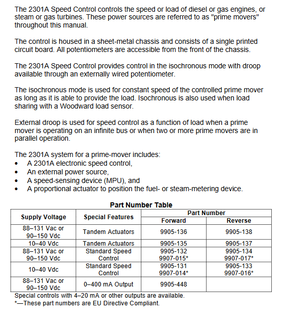
2301A offers multiple models to adapt to different applications:
Supply voltage special function forward acting model reverse acting model
88-132 Vac/90-150 Vdc series actuator 9905-136 9905-138
10-40 Vdc series actuator 9905-135 9905-137
88-132 Vac/90-150 Vdc standard speed control 9905-132/9907-015 * 9905-134/9907-017*
10-40 Vdc standard speed control 9905-131/9907-014 * 9905-133/9907-016*
88-132 Vac/90-150 Vdc 0-400 mA output 9905-448-
*Compliant with EU directive models.
The reverse acting system is designed specifically for applications equipped with Woodward EGB governors/actuators. In the event of electronic control failure, the mechanical backup governor can take over control, avoiding shutdown and improving system redundancy and safety.
Core points of installation and wiring
1. Power requirements
Low voltage model: 10-40 Vdc, low impedance power supply (such as battery) must be used, and it is strictly prohibited to draw power from high voltage sources through series resistors and Zener diodes.
High voltage models: 88-132 Vac (50-400 Hz) or 90-150 Vdc.
Important reminder: When disconnecting the battery, it is necessary to ensure that the charging device (such as the AC generator) is also disconnected from the control to prevent damage.
2. Shielding and grounding (key for EMI control)
All signal lines (MPU, actuators, auxiliary inputs, etc.) must use twisted pair shielded wires.
The shielding layer is only grounded at the controller end and connected to the chassis grounding bolt below terminal 9. The length of the grounding wire should be less than 5 centimeters.
The other end of the shielding layer must remain open and insulated, and must not be grounded at the sensor or actuator end.
Avoid laying signal lines in parallel with high current cables, and if necessary, use conduit or double-layer shielding.
3. External adjustment and options
Speed adjustment: Connect terminals 11-12 to a 100 Ω multi turn potentiometer, providing approximately ± 5% speed adjustment.
Sag adjustment: Connect terminals 13-15 to a 2k Ω potentiometer, providing a maximum sag of approximately 8%.
Minimum fuel contact point: used for normal shutdown, strictly prohibited from being used as part of emergency shutdown circuit.
Speed signal failure override: used in situations where there is no speed signal during startup (such as some steam turbines).
Idle/rated ramp contact: controls the switching between idle and rated speed, with adjustable ramp time (1-22 seconds).
Debugging and dynamic adjustment steps
1. Initial preset (before startup)
Rated speed potentiometer: Adjust counterclockwise to minimum.
Reset and gain potentiometer: placed in the middle position.
Slope time, low idle, droop (if used): Adjust counterclockwise to minimum.
Compensation for actuators:
Diesel engine/gas turbine: set to scale "2".
Steam turbine/carburetor gas engine: set to scale "6".
Start fuel limit: Adjust clockwise to maximum.
2. Startup and stability adjustment
Set the rated speed reference: The signal generator can be used to simulate the MPU frequency, or fine tune it after startup.
Check MPU signal: When turning, the voltage between terminals 7-8 should be ≥ 1.0 Vrms.
Stable operation adjustment:
Fast traveling car: Slowly decrease the gain counterclockwise.
Slow traveling car: increase reset clockwise; If it is ineffective, both the gain and actuator compensation can be fine tuned simultaneously.
Dynamic optimization:
Gradually increase the gain until the actuator becomes slightly unstable, and then reverse to stabilize.
Adjust the reset to reduce overshoot or adjustment time through sudden load/unload test response.
- OMRON
- ABB
- General Electric
- EMERSON
- Honeywell
- HIMA
- ALSTOM
- Rolls-Royce
- MOTOROLA
- Rockwell
- Siemens
- Woodward
- YOKOGAWA
- FOXBORO
- KOLLMORGEN
- MOOG
- KB
- YAMAHA
- BENDER
- TEKTRONIX
- Westinghouse
- AMAT
- AB
- XYCOM
- Yaskawa
- B&R
- Schneider
- KONGSBERG
- NI
- WATLOW
- ProSoft
- SEW
- ADVANCED
- Reliance
- TRICONEX
- METSO
- MAN
- Advantest
- STUDER
- DANAHER MOTION
- Bently
- Galil
- EATON
- MOLEX
- DEIF
- B&W
- ZYGO
- Aerotech
- DANFOSS
- Beijer
- Moxa
- Rexroth
- Johnson
- WAGO
- TOSHIBA
- BMCM
- SMC
- HITACHI
- HIRSCHMANN
- Application field
- XP POWER
- CTI
- TRICON
- STOBER
- Thinklogical
- Horner Automation
- Meggitt
- Fanuc
- Baldor
- SHINKAWA
- Other Brands
- UniOP
- KUKA
- Iba
- Beckhoff
-
 Basler SSR 125-12NF Static Regulator 9 1859 00 106
 -
 Basler BE1-BPR Breaker Protection Relay 9272000315
 -
 Basler SSR 63-12 Static Regulator 9 1859 00 101
 -
 Basler AEM-2020 Analog Expansion Module
 -
 Basler BE 25231-001 Transformer BE25231001
 -
 Basler MVC 108 Manual Voltage Control 9037000102
 -
 Basler PSS-100-Y5 Power System Stabilizer 0.1-5.0Hz
 -
 Basler Electric BE1A-25-M1G-A6T-N4V1F Sync-Check Relay
 -
 Basler Electric SR8A2B10B1A Static Voltage Regulator
 -
Basler Electric SR8A2B10B1A Static Voltage Regulator
-
Basler Electric SSR 125-12 Static Voltage Regulator 9185900102
-
 Basler Electric 90-73900-102 Power Supply (Westinghouse 2374A07G03)
 -
 Basler Electric 9400200117 Control Power Unit 12/24VDC 20W
 -
Basler Electric BE1-87G Solid State Generator Differential Relay
-
 Basler Electric BE1-32R Style C3ED1TA0S1F Solid State Protective Relay
 -
Basler Electric SR32A2B05B3E Static Voltage Regulator
-
 Basler Electric SR8A2B06B3A Static Voltage Regulator
 -
Basler MOC3502 90-72300-116 Motor Potentiometer
-
 Basler SR4A2310B1A Static Voltage Regulator
 -
 Basler Electric 90-88800-102 PRS-250 Veri-Sync Relay
 -
Basler Electric 90-88800-102 PRS-250 Veri-Sync Relay
-
Basler SR4A-2B05A3E Static Regulator SR4A2B05A3E
-
 Basler 9-0723-00-130 9072300130 Control Module
 -
 Basler BE1-79MA10A6JC0L0F Reclosing Relay
 -
 Basler CBS-377 Current Boost System 91096001
 -
Basler SR4A1B05A3A Static Regulator 480V 62.5V 10VA
-
 Basler BE159N A7ED1JC0S0F Protective Relay BE159N-0
 -
 Basler BE3-25A Auto-Synchronizer S.No. 728
 -
 Basler BE1-50 Instantaneous Overcurrent Relay G4EA1RG0N0F
 -
 Basler Electric KT3B Voltage Regulator
 -
 Basler Electric ACA2500-14GCSYM GigE Camera
 -
 Basler Electric XR2002F Voltage Regulator
 -
 Basler Electric BE1-50 Instantaneous Overcurrent Relay F2EA1PA0N5F
 -
 Basler Electric CBS 212A Current Boost System
 -
Basler Electric BE147NE3FE1PC3N3F Negative Sequence Voltage Relay
-
 Basler Electric BE1-79MA10A6JC0L0F Automatic Reclosing Relay
 -
Basler Electric BE1-59N A6E E1C B0N1F Neutral Overvoltage Relay
-
 Basler Electric MVC 108 Manual Voltage Control
 -
 Basler Electric BE1-59-A4E-E1C-A0N0F Overvoltage Relay
 -
Basler BE1-57/27R Solid State Protective Relay
-
 Basler BE3-25AX Time Overcurrent Relay
 -
BASLER ELECTRIC BE1-24/A1EF1JC1N0F / BE124A1EF1JC1N0F Overvoltage Relay
-
Basler Electric Solid State Protective Relay BE1-32R Style B2ED1PB0N0F
-
Basler BE3-51-3E1E1 9320000110 24VDC Overcurrent Relay
-
 Basler UFOV 260A Underfrequency Overvoltage Module
 -
 Basler 50F4EA1PA0N0F Instantaneous Overcurrent Relay
 -
Basler BE1-50 Instantaneous Overcurrent Relay
-
 Basler BE1-32 Solid State Protective Relay
 -
Basler SCP 250-G-60 VAR Power Factor Controller
-
Basler BE1-59N A5EE1KC0N0F Ground Fault Relay
-
Basler BE1-79A Reclosing Relay
-
Basler BE1-32R E1EA1OA0N0F Reverse Power Relay
-
 Basler DCQA-103 DCQC104-1 CMX-7D Circuit Board
 -
 Basler SSR125-12 Static Regulator 918500102
 -
Basler 90 17709 112 Regulator Control Board
-
 Basler AVC63-4 AVC634 Voltage Regulator
 -
 Basler 9 1049 04 100 PC Board Control Module
 -
Basler SR4A-2B03B3A Static Voltage Regulator
-
 Basler SR8A-2B15B3A Static Voltage Regulator
 -
 Basler KR7FFX Static Regulator 840V
 -
 Basler EL200-7 Voltage Regulator 90-660VAC 7A
 -
 Basler PRP210-1 Reverse Power Relay 9056300102
 -
 Basler SSR 63-12 Static Regulator 600VAC
 -
 Basler 9289901106 Digital Board
 -
Basler DECS100 Voltage Regulator DECS100A01
-
Basler Electric CEM-2020 Contact Expansion Module
-
Basler Electric BE3-25-1 C1 N4 Synchronizing Check Relay
-
Basler Electric ACA2000-50GM GigE Camera 2MP 50fps
-
 Basler Electric ACA2240-20GMSYM GigE Camera Sony IMX264
 -
Basler BE1-50G Ground Overcurrent Relay
-
Basler PRS250 Veri-Sync Relay
-
Basler MOC2199 Output Module
-
 Basler UFOV 260A Underfrequency Overvoltage Module
 -
 Basler BE-15482-001 Control Module
 -
Basler LSP4-7 Protective Relay
-
 Basler SCP 250-G-60 VAR Power Factor Controller
 -
Basler BE146N Negative Sequence Overcurrent Relay
-
Basler APR63-5 Automatic Voltage Regulator
-
Basler 9507900107 SR8A Retrofit Voltage Regulator
-
Basler BE1-320 Directional Power Relay
-
 Basler KR7F Voltage Regulator 9116200100
 -
Basler UFOV 260A Overvoltage Protective Module
-
 Basler AEC63-7 Analog Excitation Controller
 -
Basler 9992D90G01 Control Module
-
Basler 6966D22G01 Control Board
-
Basler 6965D40G01 Control Board
-
 Basler BE1-50/51M-104 Overcurrent Relay
 -
Basler BE1-BPR Programmable Breaker Relay
-
 BASLER Electric SSR 125-9 1256 00 102 Static Voltage Regulator
 -
Basler Electric MVC 112 Manual Voltage Control
-
 Basler Electric 9321000102 Control Module
 -
 Basler Electric RA-70-MDCT7 Rectifier Assembly
 -
 Basler Electric ACA1300-60GM GigE Camera
 -
 Basler Electric 6427C85G01 Interface Board
 -
Basler Electric 6965D05G01 Control Board
-
Basler Electric ACA2500-14UC Current Transducer
-
Basler Electric 9170206111 Protective Relay
-
Basler Electric BE1-11-G6D1M1J1P0E000 Protection Relay
-
Basler Electric BE1-50/51B-107 Overcurrent Relay
-
 Basler 9121000106 Voltage Controller
 -
 Basler B3E-E1P-A0N0F Solid State Protective Relay
 -
 Basler 9121000106 Manual Voltage Control
 -
Basler PRP320 Motor Pull-out Relay
-
 Basler SSE-N 250-9KW Shunt Exciter Regulator
 -
 Basler BE1-50-51B-107 Overcurrent Relay
 -
 BASLER ELECTRIC MVC 108 MANUAL VOLTAGE CONTROL MODULE 9 0370 00 102
 -
Basler BE1-59N-A7E-D1J-D0N0F Ground Overvoltage Relay
-
Basler BE1-46N-G1E-B8P-B0N0F Negative Sequence Overcurrent Relay
-
Basler BE1-951 Overcurrent Protection System
-
 Basler Electric MOC2199 Motor Operated Potentiometer
 -
 Basler Electric BE1-60 Voltage Balance Solid State Relay B1FA1C1M1F
 -
Basler Electric BE1-67N Directional Overcurrent Relay
-
Basler Electric PIA2400-17GM Interface Module
-
 Basler Electric V6RAB Rectifier Module
 -
Basler Electric BE1-32R Reverse Power Relay B2E E1R A0N1F
-
Basler Electric IFM-150 Firing Circuit Chassis 120V AC
-
 Basler Electric IFM-102 Firing Circuit Chassis 120V AC
 -
 Basler Electric 9170206111 NSNP Control Module
 -
Basler Electric SSR 63-12 Static Voltage Regulator
-
 Basler UFOV 260A Overvoltage Protective Module
 -
Basler SCA1300-32GM CCD Camera Lens Enclosure
-
Basler BA1-27 Under Voltage Relay
-
Basler 149D866G06 Control Board
-
 Basler 9072300130 Power Supply Module
 -
Basler CBS 305 Current Boost System
-
 Basler BE1-60 Voltage Balance Relay
 -
 Basler Electric CBS 212 Current Boost System Sensing 120/240VAC 50/60Hz 10VA
 -
 Basler MVC-300 Manual Voltage Control Unit


