
Deep Analysis of HIMA HIMax Safety Control System: Architecture, Redundancy, and Engineering Application Guidelines
Initial value: All variables that receive values from physical inputs or communications must be assigned an initial value as a safe value.
5.3 Online modification
Reload: Load modified project configurations without interrupting security related operations. This includes changing user program logic, parameters, etc., provided that the overload conditions are not violated (such as adding new variable assignments that typically require a download).
Forcing: allows replacing the current value of a variable with a forced value, used for testing programs. Attention: Forcing values may result in output errors and prolong cycle time, and must be authorized by the testing agency and used within time limits.
6. Diagnosis and maintenance
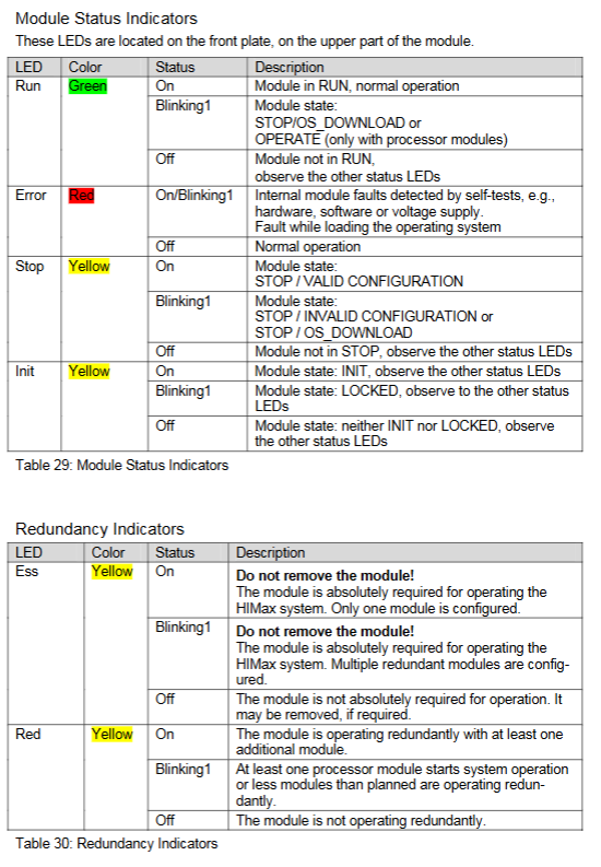
6.1 Diagnosis of LED indicator lights
The LED on the front panel of the module provides a quick overview of the system status:
Module status: RUN (green), ERROR (red), STOP (yellow), Initiat (yellow).
Redundancy status: ESS (yellow, critical module), RED (yellow, running redundantly).
System bus: Display the connection status with buses A and B (green indicates normal, flashing indicates fault).
Maintenance instructions: Force, Test, Prog.
6.2 Diagnostic History Record
Each HIMax module maintains a historical record of faults or events, divided into:
Short term diagnosis: Circular buffer, new entries overwrite old entries.
Long term diagnosis: Store user actions and configuration changes. If the entry exceeds 3 days, the new entry will overwrite the old entry; If it does not exceed 3 days, the new entry will be rejected and marked.
6.3 Temperature Monitoring
The module monitors its own temperature. The state variables display the following range:
Normal:<40 ° C
Threshold 1 exceeds: 40... 60 ° C
Threshold 2 exceeds:>60 ° C
7. Lifecycle Management: Installation and Startup
7.1 Installation and Grounding
Mechanical installation: The base plate is installed in the control cabinet, ensuring sufficient heat dissipation (it is recommended to use a fan bracket).
Grounding (PE): Functional grounding must be implemented for electromagnetic compatibility (EMC). All surfaces of HIMax components (except for pluggable modules) are conductive and must be connected to the cabinet frame through a grounding wire (such as a 16mm ² or 25mm ² yellow green wire).
7.2 Startup Process
Hardware installation: Complete all module and cable connections.
Set IP and SRS: Log in to the system bus module and processor module through SILworX, and set the System. Rack. Plot address and IP address.
Load project: Execute Download or Reload.
Start running: Set the mode switch to RUN.
7.3 Maintenance and Repair
Preventive maintenance: It is recommended to regularly replace the controller fan.
ESD protection: Only personnel with knowledge of ESD (electrostatic discharge) protection can replace modules.
Power redundancy: Supports the connection of two redundant 24 VDC power units, powered through terminals L1+/L1- and L2+/L2-.
8. System specifications and delineation
To ensure the rationality of project design, engineers need to comply with the following system boundary restrictions:
Number of resources (controllers): 1... 65534 per project
Number of baseboards: 1... 16 per resource
Processor modules: 1... 4
User program: 1... 32
Event definition: 0... 20000
I/O modules: 0... 200
SafeEthernet connection: 0... 255
Non volatile event buffer size: 5000 events
Model Supplement
X-BASE PLATE 10 01
X-BASE PLATE 15 01
X-BASE PLATE 15 02
X-BASE PLATE 18 01
X-CPU 01 (processor module)
X-SB 01 (System Bus Module)
X-COM 01 (Communication Module)
X-AI 32 02 SOE
X-DI 32 01
X-DI 32 02 (for proximity switch)
X-DI 32 03
X-DI 32 04
X-DI 32 04 SOE
X-DI 32 05 (for proximity switch)
X-DI 32 05 SOE
X-DI 64 01
X-CI 24 01
X-AO 16 01
X-DO 12 01
X-DO 12 02
X-DO 24 01
X-DO 24 02
X-DO 32 01
X-FTA AI 32 01 01
X-FTA DI 32 01 01
X-FTA DI 32 02 01
X-FTA DO 12 01 01
X-FTA DO 24 01 01
X-FTA 001 01
X-FTA 001 02
X-FTA 002 01
X-FTA 002 02
X-FTA 003 02
X-FTA 005 02
X-FTA 006 01
X-FTA 006 02
X-FTA 007 02
X-FTA 008 02
X-FTA 009 02
X-CB 008 01
X-CB 008 02
X-CB 008 03
X-CB 008 04
- OMRON
- ABB
- General Electric
- EMERSON
- Honeywell
- HIMA
- ALSTOM
- Rolls-Royce
- MOTOROLA
- Rockwell
- Siemens
- Woodward
- YOKOGAWA
- FOXBORO
- KOLLMORGEN
- MOOG
- KB
- YAMAHA
- BENDER
- TEKTRONIX
- Westinghouse
- AMAT
- AB
- XYCOM
- Yaskawa
- B&R
- Schneider
- KONGSBERG
- NI
- WATLOW
- ProSoft
- SEW
- ADVANCED
- Reliance
- TRICONEX
- METSO
- MAN
- Advantest
- STUDER
- DANAHER MOTION
- Bently
- Galil
- EATON
- MOLEX
- DEIF
- B&W
- ZYGO
- Aerotech
- DANFOSS
- Beijer
- Moxa
- Rexroth
- Johnson
- WAGO
- TOSHIBA
- BMCM
- SMC
- HITACHI
- HIRSCHMANN
- Application field
- XP POWER
- CTI
- TRICON
- STOBER
- Thinklogical
- Horner Automation
- Meggitt
- Fanuc
- Baldor
- SHINKAWA
- Other Brands
- UniOP
- KUKA
- Iba
- Beckhoff
- ADLINK
-
 Rolls-Royce R02TCN-E0L3-00 Remote Controller Features
 -
 Etel SA-IL 03-208 Linear Motor Section
 -
ETEL ILM03-060-3RA-A00 Ironless Linear Servo Motor
-
 ETEL DSCDP321-121-000 Dual Position Controller Board
 -
 Etel DSCDP121-111F-000A Dual Axis Servo Drive
 -
 Etel EA-S0M-400-40/80A-0000-00 AccurET Modular Power Supply
 -
 Etel TMB+0291-150-RO-00000-0A0 Rotor
 -
 ETEL DSCDP131-111F-000A Position Controller
 -
 ETEL DSC2P154-421F-000A Servo Drive
 -
 ETEL DSO-SER211-000 Add-On Power Board for Servo Amplifier
 -
 ETEL 613712-05 4-Axis Control Assembly
 -
 ETEL P2M-300-07/15A Accuret Position Controller
 -
 ETEL LMP07-100-3TAS-229 Motor Ruler Primary Part
 -
 ETEL 569866-03 ASME-RTMA014 Motor
 -
 ETEL DSCDP131-111-000 Dual Position Controller
 -
 ETEL DSB2S134-211E-000H Digital Servo Amplifier
 -
 ETEL DSCDP121-111F-000A DSC Dual Controller
 -
 ETEL DSC2P154-421E-000A Servo Drive
 -
 ETEL DSCDP121-111C-000A Regulator – Stable Power Control
 -
 ETEL DSC2P131-111B-000D Driver Board
 -
 ETEL ILM03-060-3RA-A00 Linear Motor
 -
 ETEL EA-S0M-300-40/80A-0090-00 Power Supply Module
 -
 Etel DSCDP131-111-000 Position Controller
 -
 ETEL DSC2P121-111E-001A Digital Servo Amplifier
 -
ETEL DSB2P101-121E-009H Position Controller
-
 ETEL IWM040-0128-00 Ironcore Linear Motor Magnetic Way
 -
 ETEL AccurET EA-S0M-400-40/80A-0000-00 Modular Power Supply
 -
ETEL LMC11-050-3TA-S10C Motion Controller
-
 ETEL LMC11-050-3TA-250A Controller Module
 -
 ETEL DSB2P101-121E-009H Digital Servo Amplifier Position Controller
 -
 ETEL AccurET Modular 400 Position Controller
 -
 ETEL DSA2 Digital Servo Amplifier
 -
ETEL DSC2P154-421-000 Servo Drive
-
 ETEL DSO-PWS121-003 Power Supply Module
 -
 ETEL 0348M-070-02D-004 Linear Encoder
 -
 ETEL DSC2P131-111-000 Linear Servo Amplifier – 10Arms/30Arms
 -
ETEL DSC2P131-121-000 Digital Servo Amplifier
-
ETEL DSB2P131-111E-000H Digital Servo Amplifier
-
ETEL DSO-PWS111-000 Power Supply Module
-
ETEL LMC11-050-3TA-S41C Linear Motor Module – High Thrust Density
-
 ETEL EA-P2M-300-07/15A Drive Specs
 -
 ETEL DSO-RAC200A-011D Dual Position Controller Rack
 -
 ETEL Short-Stroke Actuator ID809786-03
 -
 ETEL DSCDM332-111-000 Servo Controller Specs
 -
 ETEL DSCDL332-131-000A Position Controller
 -
 ETEL LMP07-100-3TAS-229 Linear Motor
 -
ETEL LMA11-120-3ZA-359C Linear Motor
-
ETEL DSA2S211ZA-018A Digital Servo Amplifier
-
 ETEL EA-P2M-300-07/15A AccurET Controller
 -
ETEL LMB06-050-2QA-239B Linear Motor Guide
-
 ETEL DSCDP334‑421‑000 Servo Drive – High‑Power Digital Controller Positioner
 -
ETEL DSCDP121‑111E‑000A Dual Driver Board – High‑Density Motion Control Module
-
 ETEL DSA2 S1B22A Digital Servo Amplifier – High‑Efficiency Drive for Industrial Motors
 -
 ETEL DSCDM342‑111‑000 Servo Amplifier – Multi‑Axis Digital Drive
 -
ETEL MWA120‑0512‑00B 512mm Linear Motor Magnet
-
ETEL EA‑P2M‑300‑07/15A‑0100‑01 AccurET Modular Position Controller – Medium‑Power Drive
-
Etel DSC2P141‑111‑000 568425‑01 Digital Servo Amplifier – Compact High‑Performance Drive
-
 Etel EA‑P2M‑400‑10/20A‑0000‑01 AccurET Modular Position Controller – High‑Voltage Drive
 -
ETEL DSC2P142‑111‑000 Digital Servo Amplifier – Compact Position Controller
-
ETEL DSDH153‑121C‑001D Digital Servo Drive – High‑Power Motion Control
-
ETEL DSB2P131 & DSO-CAN111A Servo Amplifier Set
-
ETEL DSA2S211ZA-018A Digital Servo Amplifier
-
ETEL DSMAX212-111-001 568540-01 DSMAX2 Servo Controller
-
 ETEL TMB+0291-150 Torque Motor Stator Assembly
 -
 ETEL EA-S0M-300-40/80A AccurET PSU
 -
ETEL DSO-PWR112C-000B Power Supply Module
-
ETEL DSC2P141-111-000 Linear Servo Amplifier
-
ETEL DSB2S154-211-000H Servo Amplifier
-
ETEL DSCDP121-122-000 Digital Controller
-
ETEL DSCDP121-111E-000A Dual Position Controller
-
ETEL DSCDM332-111-000 Linear Servo Controller
-
 ETEL DSB2P134-111E-000H Servo Amplifier
 -
ETEL DSCDP132-111-000 Control Board Guide
-
 ETEL DSB2S154-211E-000H Servo Amplifier
 -
ETEL EA-SOM-300-40/80A Power Supply Module
-
ETEL ILM12-060-3PD-R20C Linear Motor with IWM Ways
-
 ETEL P2M-300-07 AccurET Position Controller
 -
ETEL DSB2P124-111E-000H Servo Amplifier
-
 ETEL EA-P2M-048-05/10A Position Controller
 -
 ETEL EA-S0M-300-40/80A Power Supply Module
 -
ETEL MWA070-0256-20B Linear Motor Magnet Guide
-
ETEL MWD070‑0128‑21A Linear Motor – Compact Ironless Linear Motor for High‑Speed Precision
-
ETEL DSB2P124‑211E‑000H Digital Servo Amplifier – 300 VDC Slave Drive for High‑Voltage Systems
-
ETEL MWD100‑0128‑00B Linear Motor – High‑Force Ironless Linear Motor for Precision Motion
-
ETEL AccurET EA‑S0M‑400 & P2M‑400‑05/10A Drive Module
-
ETEL EA‑S0M‑400‑40/80A‑0000‑00 AccurET Power Supply – High‑Power DC Supply for Motion Systems
-
ETEL MWA050‑0128‑20B Linear Motor Magnet – High‑Force Magnet Assembly for Linear Motors
-
ETEL DSB2S121‑111E‑000H Digital Servo Amplifier – High‑Current Drive for Demanding Motion
-
 ETEL DSCDM332‑111C‑000B Digital Position Controller DSCDM – High‑Density Motion Module
 -
ETEL EA‑P2M‑048‑2.5/5A‑0100‑01 AccurET Modular Position Controller
-
 ETEL DSC2P121-111E-001A Digital Servo Controller – High‑Precision Motion Control
 -
ETEL MWA050-0128-20B Linear Motor Magnet
-
 ETEL DSB2P142-111E-000H Drive Specs
 -
 ETEL DSB2S234-111E-000H Servo Amplifier
 -
 ETEL EA-P2A-400-10-20A Position Controller
 -
ETEL DSB2 Digital Servo Amplifier Controller DSB2P142-111E-000H SN 014661437
-
ETEL EA-S0M-400-40/80A-0000-00 AccurET Power Supply Module 650140-01
-
ETEL DSB2P131-111E-000H Servo Amplifier
-
ETEL EA-P2M-400-10/20A AccurET Controller
-
ETEL DSDP324-322F-000C Dual Motor Driver
-
ETEL DSB2S154-211E-000H Digital Servo Amplifier Drive
-
ETEL DSO-PWS111B-000C Power Supply Board 1130E-070-018
-
ETEL DSCDP324-322G-000A Servo Amplifier
-
ETEL DSB2P142-111E-000H Servo Amplifier Drive
-
 ETEL EA-P2M-400-15/40A & EA-S0M-400 Drive Set
 -
ETEL DSB2P142-111E-000H Digital Servo Amplifier
-
ETEL LMG15-070-3QC-H11 Linear Motor
-
 ETEL TMA0140-070-3RB-S62B Torque Motor
 -
ETEL DSA2S211ZA Digital Servo Amplifier
-
ETEL AccurET EA-P2M-300-4/7.5A-0100-01 Modular Position Controller
-
 ETEL DSCDL332-131C-000A Servo Control Board
 -
ETEL DSCDP324-322F-000C Dual Motor Driver
-
 ETEL EA-P2M-400-10/20A Position Controller
 -
ETEL DSC2P121 and DSO-HIO33 Servo Amplifier Set
-
 ETEL EA-P2M-400-15/40A AccurET Drive
 -
ETEL EA-P2M-300-07/15A Position Controller
-
ETEL EA-P2M-048-05/10A-0100-01 Servo Drive
-
 ETEL EA-S0M-300-40/80A Servo Drive Guide
 -
ETEL DSB2P131-111E-000H Digital Servo Amplifier
-
ETEL DSCDP334-421-000 Servo Drive Guide
-
ETEL EA-S0M-300-40 80A-0000-00 Motion Control Module
-
 ETEL UltimET Light Motion Controller EU-LGP-0-0-1000-01 Multi-Axis
 -
 ETEL DSO-RAC601-029 Controller Rack
 -
ETEL DSMAX212-121C-000C Board
-
 ETEL DSCDL132-212B-000C Position Controller
 -
ETEL TMB0291-050-3TDS-E82 Torque Motor
-
 ETEL DSMAX212-121-000 Board
 -
ETEL DSB2P131-111E-000H Digital Servo Controller Amplifier Unit


