
HIMA HIQuad X System Manual: Comprehensive and in-depth analysis of HIMA SIL 3 safety automation system
HIQuad X System Manual: Comprehensive and in-depth analysis of HIMA SIL 3 safety automation system
1. System Overview and Core Advantages
HIQuad X is the next-generation safety related programmable electronic system (PES) launched by HIMA, designed to meet the dual requirements of high availability and functional safety in the industrial sector.
Core Features
Safety level: The system design complies with IEC 61508 SIL 3 and EN ISO 13849-1 PL e standards.
Programming tools: Use validated SILworX programming tools for configuration, monitoring, and programming.
Architecture: Supports the principles of "de excitation trip" and "excitation trip", suitable for fire alarm systems (compliant with DIN EN 54-2 and NFPA 72) and explosion-proof areas (Zone 2).
Compatibility: Supports existing HIQuad I/O modules to ensure a smooth transition for system upgrades.
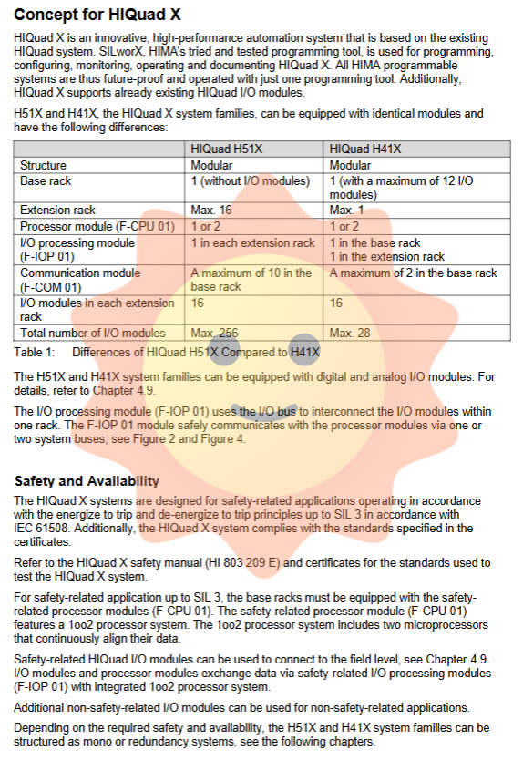
2. System architecture: H51X and H41X series
The HIQuad X adopts a modular design and is mainly divided into two series: H51X (high-performance, highly expandable) and H41X (compact, independently expandable).
2.1 H51X Series (Extended System)
Suitable for scenarios with large-scale I/O requirements.
Structure: 1 basic rack+up to 16 expansion racks.
I/O capacity: up to 256 I/O modules, totaling up to 4096 I/O points.
Expansion rack: Each expansion rack supports up to 16 I/O modules.
Communication module: The basic rack supports up to 10 communication modules.
2.2 H41X series (compact system)
Suitable for applications with limited space or moderate I/O points.
Structure: 1 basic rack+up to 1 expansion rack.
I/O capacity: up to 28 I/O modules, totaling up to 224 I/O points.
Basic rack: The basic rack comes with 12 I/O slots.
Communication module: The basic rack supports up to 2 communication modules.
3. List of Key Hardware Components and Models
The flexibility of the HIQuad X system comes from its rich modular components. The following are the key hardware models and their functions listed in the system manual.
3.1 Core Control and Processing Module
Component Model Function Description
F-BASE RACK 01 H51X system basic rack, including H51X backplane.
F-BASE RACK 02 H41X system basic rack, including H41X backplane.
F-BASE RACK 11 expansion rack backplane, supporting maximum I/O expansion.
F-CPU 01 processor module. Integrate 1oo2 processor architecture (dual microprocessor continuous data verification) to ensure SIL 3 safety integrity.
F-IOP 01 I/O processing module. Manage the I/O bus, connect I/O modules with processor modules, and be responsible for transmitting I/O watchdog signals.
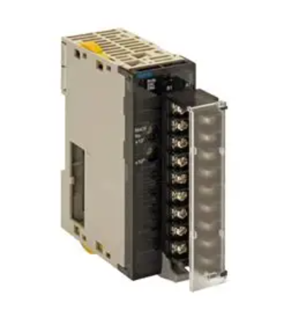
F-COM 01 communication module. Equipped with 2 Ethernet interfaces and 1 fieldbus interface for secure or standard communication with external systems.
3.2 Power Supply and Distribution Module
Component Model Function Description
F-PWR 01 power supply unit (24V/5V). Each basic rack can be configured with up to 5 (H51X) or 2 (H41X) for redundancy.
F-PWR 02 buffer module. Used to compensate for voltage drops in expansion racks and ensure independent redundant power supply at the I/O level.
F 7133 power distribution module. Used for fuse protection and 24V distribution of I/O modules.
K 7205/7212/7213/7214 HIMA power distribution components provide redundant power supply solutions with decoupling diodes and main filters.
H 7034 main filter, used to protect 24V power supply from transient interference.
3.3 I/O Module Model List
HIQuad X supports a wide range of I/O modules, including digital (DI/DO), analog (AI/AO), relays, and counters.
Digital input module
F 3221 (Z 7116/3221): 16 channel digital input
F 3236 (Z 7116/3236): 16 channel digital input, SIL 3
F 3237 (Z 7108/3237): 8-channel digital input, SIL 3
F 3238 (Z 7008/3238): 8-channel digital input; SIL 3; (Ex)i
F 3240 (Z 7130/3240): 16 channel digital input 110 VDC, SIL 3
F 3248 (Z 7130/3248): 16 channel digital input 48 VDC, SIL 3
Digital output module
F 3322 (Z 7136/3322): 16 channel digital output 0.5 A, SIL 3
F 3325 (Z 7025/3325): 6-channel power supply module
F 3330 (Z 7138/3330): 8-channel digital output 0.5 A, SIL 3
F 3331 (Z 7138/3331): 8-channel digital output 0.5 A, SIL 3
F 3333 (Z 7134/3333): 4-channel digital output 2 A, SIL 3
F 3334 (Z 7134/3334): 4-channel digital output 2 A, SIL 3
F 3335 (Z 7035/3335): 4-channel digital output; (Ex)i
F 3349 (Z 7150/3349): 8-channel digital output 0.5 A, SIL 3
F 3422 (Z 7139/3422): 8-channel relay 60 VDC, SIL 3
F 3430 (Z 7149/3430): 4-channel relay 110 VDC, SIL 3
Analog input and output module
F 6215 (Z 7127/6215): 8-channel analog input
F 6217 (Z 7127/6217): 8-channel analog input, SIL 3
F 6220 (Z 7062/6220): 8-channel thermocouple; (Ex)i
F 6221 (Z 7063/6221): 8-channel analog input; (Ex)i
F 6705 (Z 7126/6705): 2-channel analog output
F 6707 (Z 7126/6706): 2-channel analog output
other modules
F 3224A (Z 7114/3224): 4-channel digital input; (Ex)i
F 3248 (Z 7130/3248): 16 channel digital input 48 VDC
F 3325 (Z 7025/3325): 6-channel power supply module
F 3422 (Z 7139/3422): 8-channel relay 60 VDC
4. Security and availability
The core design of HIQuad X is to maximize availability through redundant architecture while ensuring safety (SIL 3).
4.1 Safety Integrity Level (SIL)
Processor: F-CPU 01 adopts a 1oo2 architecture (dual processor cross comparison) to ensure that processor failures do not result in the failure of safety functions.
Communication: Safety related communication is conducted through the SafeEthernet protocol.
I/O module: The I/O module integrates the 1oo2 processor system through F-IOP 01 to ensure the safety related accuracy of signal acquisition and output.
4.2 Redundant Configuration
HIQuad X supports all-round redundancy:
Processor redundancy: Supports up to 2 processor modules (F-CPU 01) to run synchronously, achieving seamless hot standby.
I/O module redundancy: Supports module redundancy and channel redundancy. When a fault occurs, redundant modules take over and the system continues to operate.
System bus redundancy: Dual system buses (A/B) ensure high availability of communication links.
Power redundancy: Dual 24V power supply (L1+, L2+) combined with decoupling diodes to ensure that a single power supply failure does not affect system operation.
4.3 Noise Suppression
The system has built-in noise suppression function to cope with transient interference (such as voltage fluctuations).
Principle: Within the configured fault tolerance time (FTT) and safety time, the system automatically shields brief fault signals, maintains the last valid value, and avoids unnecessary system shutdown.
Configuration: Calculate the maximum and minimum noise suppression time using the "Safety Time" and "Watchdog Time" parameters in SILworX.
5. Power management and specifications
5.1 Power Requirements
Input voltage: 24V DC (standard 24V, allowable deviation -15% to+20%).
Power standard: Must comply with SELV or PELV standards.
Buffer capability: The power unit must be able to withstand a voltage drop of up to 20ms (if not met, F-PWR 02 buffer module must be used).
5.2 5V power supply distribution
The HIQuad X system provides independent 5V power supply for the I/O module and F-IOP module.
The 5V power supply is generated in the base rack through the F-PWR 01 unit and allocated to the I/O expansion rack.
Cable requirements: The resistance of the 5V power supply line must meet specific voltage drop requirements (H51X system resistance ≤ 40 m Ω per 12m length), and it is recommended to use shielded cables (LIY-CY).
5.3 Heat consumption calculation
When designing the heat dissipation of the control cabinet, it is necessary to consider the power consumption of all modules. HIQuad X provides a natural convection heat consumption calculation formula based on ambient temperature and installation method:
ΔTmax = Pv / (k * A)
Among them, Pv is the total power consumption of electronic components, k is the heat transfer coefficient (about 5.5 W/m ² K for steel cabinets), and A is the effective heat dissipation area.
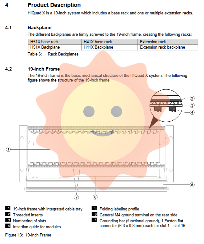
6. Installation and mechanical specifications
6.1 Environmental conditions
Parameter specifications
Working temperature 0...+60 ° C
Transportation/storage temperature -40...+70 ° C
Pollution level 2
Altitude<2000 meters
Protection level IP20 (standard), if it needs to be installed in an IP54 cabinet according to EN 60204.
6.2 Mechanical Installation
Size: Complies with the 19 inch standard.
Installation direction: I/O modules must be installed vertically.
Grounding and shielding: The surface of the system components has been treated with conductive chrome plating to achieve ESD protection. The rack and cabinet frame must be effectively connected through the equipotential grounding bar (25 mm ² grounding wire) provided by HIMA.
6.3 Ventilation Strategy
It is recommended to use HIMA K 9202B cabinet fan (top mounted) for forced ventilation.
The K 9203A rack fan is required for forced cooling below the expansion rack block.
The average heat consumption of the system through natural convection is about 300W (multiple cabinets arranged side by side), and adding fans can significantly improve the heat dissipation capacity (supporting a maximum total power consumption of 1000W).
7. Programming and Configuration (SILworX)
Tools: Use SILworX for project configuration, variable management, logic programming, and fault diagnosis.
Variable management: Supports global and local variables, and supports initial value setting (safety related variables must have safety initial values set).
Force: Used for testing and debugging, supports global and local force, and can set time limits and timeout actions (stop force or stop program).
User management: Supports multi-level user permission management (security administrator, read-write, read-only), and PES (controller) user account management (up to 10 user groups).
- ABB
- General Electric
- EMERSON
- Honeywell
- HIMA
- ALSTOM
- Rolls-Royce
- MOTOROLA
- Rockwell
- Siemens
- Woodward
- YOKOGAWA
- FOXBORO
- KOLLMORGEN
- MOOG
- KB
- YAMAHA
- BENDER
- TEKTRONIX
- Westinghouse
- AMAT
- AB
- XYCOM
- Yaskawa
- B&R
- Schneider
- Kongsberg
- NI
- WATLOW
- ProSoft
- SEW
- ADVANCED
- Reliance
- TRICONEX
- METSO
- MAN
- Advantest
- STUDER
- KONGSBERG
- DANAHER MOTION
- Bently
- Galil
- EATON
- MOLEX
- DEIF
- B&W
- ZYGO
- Aerotech
- DANFOSS
- Beijer
- Moxa
- Rexroth
- Johnson
- WAGO
- TOSHIBA
- BMCM
- SMC
- HITACHI
- HIRSCHMANN
- Application field
- XP POWER
- CTI
- TRICON
- STOBER
- Thinklogical
- Horner Automation
- Meggitt
- Fanuc
- Baldor
- SHINKAWA
- Other Brands
- UniOP
- KUKA
- Iba
-
 ABB SCC-C 23070-0-10232110 gas cooler
 -
 Sick LGTN101-521 CPU Module
 -
 Okuma 1911-2836 PLC Circuit Board
 -
 Mitsubishi Melsec PM-120M PLC
 -
 Omron F210-C15 Vision Mate Controller System
 -
 Siemens 7ML5110-1GD07-4AF3 Ultrasonic Level Gauge
 -
 ABB Pluto S46 V2 Safety Relay
 -
 Omron Z3RN-5A Optical Serial Link
 -
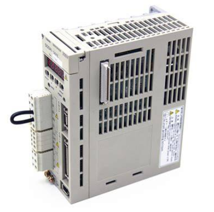
 Omron R7D-APA3H 30W Servo Drive
 -
 Giddings Lewis 502-03638-41R3 PLC Processor
 -
 Omron SCY-P1 Sequencer Controller
 -
 Siemens C98043-A7002-L1-13 PCB Board
 -
 SACS TECNICA Palletizer PC PLC Control System
 -
 AutomationDirect T1F-14THM PLC Module T1F14THM
 -
 OMRON C200H-AD003 Analog Input Unit PLC Module
 -
 Applied Materials 0010-A0000 Electricity Box PLC 200mm
 -
 ABB RVT-6 Power Factor Controller RVT6
 -
 Allen-Bradley 2094-BC01-MP5-M Kinetix 6000 Axis Module
 -
 OMRON FQM1S-MC233 Motion Controller PLC Module
 -
 OMRON C200H-SNT31 PLC Special I-O Module
 -
 Yaskawa SGMPH-04AAA61D-OY Servo Motor 400W 200V
 -
 Yaskawa SGMGH-09DCA6F-OY AC Servo Motor 850W 400V
 -
 REFU ELEKTRONIK SR17002 PLC Logic Module Circuit Board
 -
 Siemens 6DP1231-7AA PLC Board Module Industrial Control
 -
 ABB SACE ISOMAX S3 N 160 Molded Case Circuit Breaker
 -
 OMRON C120-SC024-V1 SYSMAC C120 Compact PLC Unit
 -
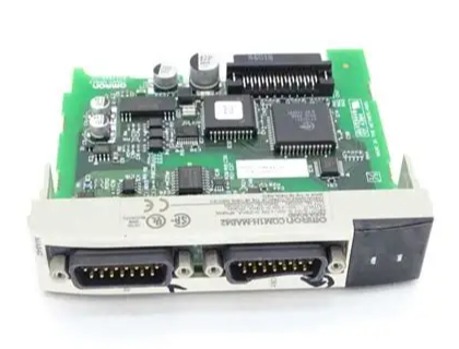
 OMRON CJ1W-SCU41-V1 Serial Communication Unit PLC Module
 -
 OMRON 3G3MX2-A4110-ZV1 MX2 Variable Frequency Drive
 -
 Yaskawa SGDH-04AE-OY Sigma-II Servo Driver 400W 200V
 -
 OMRON CQM1-AD041 Analog Input Module PLC I/O Unit
 -
 Delta Omega XML2-0060-45-4/S-A Servo Drive
 -
 Omron CJ1W-AD041 Analog Input
 -
 Omron CJ1W-NC271 Position Control Unit
 -
 Omron CJ1G-CPU45H PLC CPU
 -
 Omron CJ1W-EIP21 EtherNet/IP Unit
 -
 Omron F210-C15 Vision Mate Controller
 -
 Omron CQM1H-ADB21 Analog I/O Board
 -
 Omron GRT1-PRT PROFIBUS DP-V1 Adapter
 -
 Omron CP1H-Y20DT-D PLC CPU
 -
 TE.CO TFX 4G 1.5 Grey Cable 470m
 -
 Yaskawa SGDH-04AE-OY Servo Driver 400W 200V
 -
 OMRON CJ1H-CPU66H V4.0 PLC CPU
 -
 OMRON R7M-A10030-BS1 Servo Motor 200W 100V
 -
 OMRON FQM1-MMA21 Motion Controller
 -
 Yaskawa SJDE-08APA Servo Amplifier
 -
 OMRON CQM1-AD041 Analog Input Unit
 -
 Siemens OCI55 Dialogue Module Landis
 -
 OMRON F350-C10E Image Processing Unit
 -
 OMRON NT10S-SF121 HMI Terminal
 -
 SIEMENS 3RB1262-0LB31 Overload Relay
 -
 OMRON YASKAWA SGDS-02A12A Servo Drive
 -
 TE.CO TFX 4G 1.5 Grey Cable ST 500m
 -
 FANUC A16B-3200-0362 PCB Control Board
 -
OMRON CQM1-ARM21 Analog Output Unit
-
 Allen-Bradley 1788-EN2DN Ethernet DeviceNet Gateway
 -
 Siemens 3VL9440-7EE40 3VL4740-2AA46-0AA0 Circuit Breaker
 -
 OMRON CJ1W-AD041-V1 Analog Input Unit
 -
 OMRON CQM1-AD041 CQM1-IPS02 Analog Input Power Supply
 -
 Texas Instruments System 505 PLC 525-110 525-1102
 -
 OMRON CQM1-AD042 Analog Input Unit
 -
 Yaskawa SGDH-04AE-OY Servo Driver 200V 400W
 -
 CTI 2512 75W Power Supply for CTI 2500
 -
 Omron F300-B5 Image Processing Unit
 -
 Mitsubishi 15050-PR01A PLC Board
 -
 Omron CQM1-TC101 Temperature Controller
 -
 SCE M68-2000 2 Axis Motion Controller HW 2.3/B
 -
 Omron 3Z4SP-C22 Visual Positioning Sensor
 -
 Omron 3G3SV-BB007-E 0.75kW VFD
 -
 CML 6622 IRD Entek AW10528 Vibration Monitor
 -
 Omron CP1L-EL20DR-D PLC CPU
 -
 TE.CO TFX 4G 1.5 Grey Cable 500m
 -
 Mitsubishi Electric 3BK23057 Circuit Board Module
 -
 OMRON FQM1-MMP21 Motion Control Module
 -
 OMRON CP1E-E40SDR-A Micro PLC CPU Unit
 -
 KEBA CU201 PLC Control Unit
 -
 OMRON F150-C10E-2 Vision Sensor Controller
 -
 YASKAWA SGDH-04AE-OY Sigma-II Servo Driver
 -
 OMRON CS1H-CPU65-V1 PLC Central Processing Unit
 -
 OMRON NB7W-TX01B Interactive Display HMI
 -
 OMRON C500-TU002E Programmable Logic Controller Timer Unit
 -
 OMRON C200HW-PRT21 PROFIBUS DP Slave Unit
 -
 ExcelTech MX-5-S-I-6-4 Static Transfer Switch
 -
 Allen-Bradley 100-B300ND3 Contactor 304A 600V
 -
 Pasaban MTC-3052 Fast I/O PLC Card
 -
 OMRON CQM1-TC101 Temperature Control Unit
 -
 OMRON 3G3SV-BB007-E VFD 0.75kW 220V
 -
 OMRON CQM1H-MAB42 PLC Module
 -
 OMRON R88M-K75030T-S2 Servo Motor
 -
 Yaskawa SGMAH-03DAAA61 Servo Motor 200V 300W
 -
 OMRON F300-P Power Supply Unit
 -
 Land System 4 M1 Thermometer 65071800C-L35-A50
 -
 Yamatake MAH10-ME0100 ME-NET Module
 -
 Siemens Simatic 505 16 Slot PLC Rack
 -
 Yaskawa SGDH-02AE-OY Servo Driver 200W
 -
 SCE M68-2000 2-Axis Motion Controller
 -
 Zenith Controls K-1201 Transfer Switch Controller
 -
 Yaskawa SGDH-02AE-OY 200W Servo Driver
 -
 Yaskawa SGMAH-02AAA61D-0Y 200W Servo Motor
 -
 Schneider TSX P573634M Modicon Premium CPU
 -
 Siemens 6FX5002-5DN31-1DA0 Power Cable
 -
 Omron CJ1G-CPU43H CPU Unit 30K Steps
 -
 OMRON C28P-EDR-D PLC Unit
 -
 SIEMENS S7-300 PLC System
 -
 Schneider TP400-PLC-1411 Board
 -
 Siemens 6FC5203-0AF00-0AA3 Panel
 -
 ALLEN BRADLEY 1754-L28BBB GuardPLC
 -
 Omron E6C3-AG5B-C Encoder
 -
 SCE M68-2000/5 CNC Controller
 -
 SCHNEIDER TM2ALM3LT Module
 -
 OMRON C200H-OV001 Voice Module
 -
 OMRON R88M-H30030 Servo Motor
 -
 Bosch RD500 Indramat Servo Drive RD51.2-4B
 -
 Siemens 6SE7090-0XX84-0AH2 T300 Module
 -
 Omron GRT1-TS2P SmartSlice Thermocouple Input
 -
 Xaar XP55500016 XUSB Drive Electronics
 -
 Siemens 6SL3210-1SE21-8UA0 PM340 Power Module
 -
 Mitsubishi GT2708-VTBA Touch Display 8.4 Inch
 -
 Pasaban Fast I/O MTC-3052 PLC Card
 -
 ABB ACS355-01U-02A4-2 VFD 0.37kW
 -
 Yamatake MAH20-PC2100 Processor Module
 -
 Allen Bradley 1774-P1 PLC Power Supply
 -
 Yaskawa SGDH-04AE-OY 400W Servo Driver
 -
 Omron CPH-X40DT1-D PLC CPU Unit
 -
 Pilz PNOZ mm0.2p Safety PLC Mini 772002
 -
 Siemens 6SL3555-OPR01-0AA0 Sinamics G110M Panel
 -
 Sanyo PLC-XTC50L LCD Projector
 -
 SCE M68-2000 2-Axis Motion Controller
 -
 Omron CS1W-CT021 High-Speed Counter Unit


