
Watlow Anafaze CLS200 Series Controller
Analog output: No onboard analog output, requires optional module expansion (DAC/SDC).
3. Communication and Power Supply
Serial communication: EIA/TIA-232 or EIA/TIA-485, baud rates 2400/9600/19200 can be set, supports ANSI X3.28-1976 (compatible with Allen Bradley PLC/2), Modbus ® RTU protocol;
Power requirements: 15-24V DC ± 3V, maximum 1A (loaded), 300mA (unloaded), optional 120/240V AC to 15V DC adapter (UL) ® Class 2 certification).
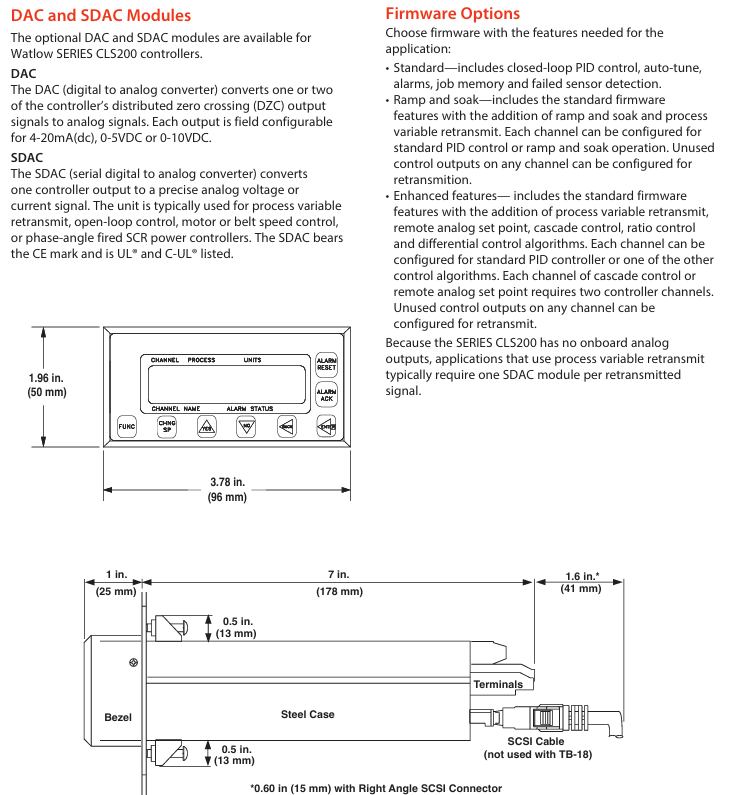
Optional modules (DAC/SDC)
Used to convert the digital output of the controller into analog signals to meet specific control requirements:
Module type, functional specifications, application scenarios
DAC (Digital to Analog Converter) 1-2 distributed zero crossing trigger (DZC) outputs are converted into analog signals, each of which can be configured as 4-20mA DC, 0-5V DC, or 0-10V DC for simple analog signal conversion (such as valve opening control, ordinary speed regulation)
SDAC (Serial Digital to Analog Converter) 1 high-precision analog output (voltage/current), supporting process variable retransmission, open-loop control, motor/belt speed regulation, phase triggered SCR power control, with CE/UL ®/ C-UL ® Certification of high-precision signal requirements (such as precision instrument temperature control, remote monitoring of process variables)
Module power configuration
Power option specifications support module quantity
A has no power supply-
B 120V AC 60Hz wall mounted power supply (16V DC 300mA) with up to 10 dual DAC modules
H 120/240V AC 50/60Hz adapter (15V DC 1.2A) with up to 12 dual DAC modules
L 120/240V AC 50/60Hz adapter (5V DC 3A) with up to 10 SDAC modules
Ordering Rules and Selection Guide
1. Ordering code for the main controller (Series CLS200)
The code structure consists of 10 bits, and the key bits have the following meanings (see the document "Ordering Information" for the complete structure):
Code bit meaning optional values
② ③ Number of circuits: 04=4 circuits, 08=8 circuits, 16=16 circuits
④ Controller type (firmware) 1=standard, 3=slope insulation, 4=enhanced, C=customized
⑤ Terminal board 0=SCSI interface only, 1=18 pin terminal block (CLS204/208), 2=50 pin terminal block (including 3-foot SCSI cable)
⑥ Power adapter 0=none, 3=120/240V AC to 15V DC (UL) ® Class 2)
⑦ SCSI cable 0=none (option 0/1), 1=6-foot straight head, 2=3-foot elbow
⑧ Serial communication cable 0=none, 1=10 feet DB-9 female head/bare wire
⑨ Communication jumper 0=EIA/TIA-232, 1=EIA/TIA-485, 2=EIA/TIA-485 terminal matching
⑩ Special input 0/00=thermocouple only/-10~60mV, N/NN=current/voltage/RTD quantity (N is the quantity), XX=custom code
2. Special input selection (10 digits)
If you need to support RTD and linear current/voltage input, you need to specify a special input code:
Special input code type applicable to controllers
20 RTD1 (-100~275 ℃, 0.1 ℃ resolution) CLS204/208
21 RTD2 (-120~840 ℃, 1 ℃ resolution) CLS204/208
44 0-20mA/4-20mA DC Full Series
55 0-5V DC Full Series
56 0-10V DC Full Series
3. DAC/SDAC module ordering code
Code structure: CLSSI+special input type+start channel+end channel, for example, "CLSSI 44 01 04" represents 4-20mA input, covering 1-4 channels.
- OMRON
- ABB
- General Electric
- EMERSON
- Honeywell
- HIMA
- ALSTOM
- Rolls-Royce
- MOTOROLA
- Rockwell
- Siemens
- Woodward
- YOKOGAWA
- FOXBORO
- KOLLMORGEN
- MOOG
- KB
- YAMAHA
- BENDER
- TEKTRONIX
- Westinghouse
- AMAT
- AB
- XYCOM
- Yaskawa
- B&R
- Schneider
- KONGSBERG
- NI
- WATLOW
- ProSoft
- SEW
- ADVANCED
- Reliance
- TRICONEX
- METSO
- MAN
- Advantest
- STUDER
- DANAHER MOTION
- Bently
- Galil
- EATON
- MOLEX
- DEIF
- B&W
- ZYGO
- Aerotech
- DANFOSS
- Beijer
- Moxa
- Rexroth
- Johnson
- WAGO
- TOSHIBA
- BMCM
- SMC
- HITACHI
- HIRSCHMANN
- Application field
- XP POWER
- CTI
- TRICON
- STOBER
- Thinklogical
- Horner Automation
- Meggitt
- Fanuc
- Baldor
- SHINKAWA
- Other Brands
- UniOP
- KUKA
- Iba
- Beckhoff
- ADLINK
-
 Basler IFM-105 Firing Circuit Chassis 9324100105
 -
 Basler SR4A2B05B3A Static Voltage Regulator
 -
 Basler BE151G1EB6PB0N0F Protective Relay
 -
 Basler BE1-59 Electric Over Voltage Relay
 -
 Basler 277 Static Programmable Powerline Carrier Channel
 -
 Basler BE1-32R D1E A1P A0N1F Power Relay
 -
Basler SR4A1B07B3A Static Voltage Regulator
-
 Basler Electric BE1-700 Digital Protective Relay
 -
Basler Electric SR8A-2B01B3A Static Voltage Regulator
-
 Basler Electric SR4A-2B01B3E Static Voltage Regulator
 -
 Basler Electric 9017709102 PC Board
 -
Basler Electric SR4A-2B01B3A Static Voltage Regulator
-
 Basler Electric PRS-250 Veri-Sync Relay
 -
 Basler Electric 9066800102 Excitation Support System
 -
Basler Electric BE1-87G Generator Differential Relay 9 1708 18 100
-
 Basler Electric 36T865-2 BE03752001 Power Supply
 -
 Basler Electric M-300 149D940G02 Power Supply
 -
 Basler Electric ACA2040-25GM 4Mp 25Fps Area Scan Camera
 -
 Basler BE1-87G-S1A-A1C-A0N0 Differential Relay
 -
 Basler SR8A-2B06B3E Static Regulator SR8A2B06B3E
 -
 Basler SCP-210 Frequency Controller 9095400100
 -
 Basler BE1-59-A3E-A1J-N1N3F Overvoltage Relay BE159A3EA1JN1N3F
 -
 Basler 9 2011 11 100 Bracket Mounted Terminal Unit
 -
Basler 9 1606 00 101 Voltage Regulator
-
 Basler CBS-377 Current Boost System 9109600102
 -
 Basler 8650C72 Exciter Control Module PCB Rev 5
 -
 Basler C2EE1PA0N1F BE1-32R Reverse Power Relay
 -
 ADLINK HPCI-14S12U - Industrial Control Backplane 12PCI Backplane PCI-14S Passive Backplane
 -
-0010.png) ADLINK PCIe-GIE74C - image acquisition card 4-CH GigE Vision PoE+ Frame Grabber
ADLINK PCIe-GIE74C - image acquisition card 4-CH GigE Vision PoE+ Frame Grabber -
-0010_1.png) ADLINK PCI-8164 - control card 4-Axis Advanced Motion Controller Board
ADLINK PCI-8164 - control card 4-Axis Advanced Motion Controller Board -
 ADLINK PCIe-U304 - 4 Port USB3 PCIe Frame Grabbers USB Screw Hole Card
 -
 ADLINK PCI-9112 - Multi-Function Data Acquisition Card DAQ Card
 -
 ADLINK PCI-7432 - 51-12013-0A50 4-CH Isolated Numérique I/O PCI Cartes Digital I/O Card
 -
 ADLINK PCA-6106P3-0C1 REV.C1 - backplane 6-Slot Passive Backplane Board
 -
 ADLINK PCI-7224 - 24-CH Opto-Isolated Digital I/O PCI Board
 -
 ADLINK CPCI-7433R(G) - Digital Input Board Rear I/O CompactPCI Card
 -
 ADLINK EBP-13E4 - 51-46703-0A30 Industrial PC Backplane Passive Backplane
 -
 ADLINK PCIE-HDV62 - Image acquisition card High Definition Video Frame Grabber
 -
 ADLINK EBP-13E4 - 51-46703-0A30 Industrial Backplane Board Passive Backplane
 -
 ADLINK 90111-B1 / CPCI-6770 - PCB CPU MODULE CompactPCI Single Board Computer
 -
 ADLINK PCI-7248 - DATA ACQUISITION PCI CARD 48-CH Parallel Digital I/O Board
 -
 ADLINK PCI-7230 - 51-12003-0a50 board PCI7230 32-CH Isolated Digital I/O Card
 -
 ADLINK PCI2A000CB - 51-20000-0B30 Multi-Function DAQ Card Baseboard
 -
 ADLINK PCI-8134-005 - 4-Axis Motion Controller Card
 -
 ADLINK PCI-7224 - 24-CH Opto-Isolated Digital I/O PCI Card
 -
 ADLINK PCI-7434 - 64-CH Isolated Digital Output Card
 -
 ADLINK PCI-8132 - motion control card 2-Axis Servo & Stepper Controller
 -
 ADLINK PCI-8134 - Motion Controller PCI Card 4-Axis Controller Board
 -
 ADLINK PCI-8164 - Motion Control Card 51-12406-0A40 4-Axis Controller
 -
 ADLINK 51-12001-0C20 - Circuit Board Data Acquisition Interface Module Hardware
 -
 ADLINK NuPR0-840 - industrial control motherboard Full-Size PICMG CPU Board
 -
 ADLINK PCI-7444 - 51-12023-0A10 card 128-CH Isolated Digital Output Board
 -
 ADLINK PCI-1612B - data acquisition card 4-Port RS-232/422/485 Serial Communication Card
 -
 ADLINK PCI-6208V 009 - 8/16-CH 16-Bit Analog Output Cards PCB-I-E-482=6BX3
 -
 ADLINK NUPRO-935A/LV - industrial control motherboard Full-Size PICMG SBC Board
 -
 ADLINK PCI-9114DG - Multi-Function DAQ Card Data Acquisition PCI Card
 -
 ADLINK ACL-7130 - Data acquisition card Isolated Digital I/O Board
 -
 ADLINK ABX-6300D-4E1-BP - board ABX6300D4E1BP Video Interface Expansion Card
 -
 ADLINK CPCI-6940 - CPCI-6940/D1539/M16-0(EA)-000E 6U CompactPCI Processor Board
 -
 ADLINK NuPRO-760 - industrial control motherboard Half-Size PICMG SBC CPU Board
 -
 ADLINK IMB-M42H (G)-0020 - industrial control motherboard LGA1155 Micro-ATX Mainboard
 -
 ADLINK RTV-24 / PCI-MP4S - 51-12519-1C30 4-Channel Real Time Video Capture Board
 -
 ADLINK PCI-8134 - 4-Axis Servo & Stepper Motion Controller Card
 -
 ADLINK MXC-6101D - V.PC000.002.ST.00 Box PC Configurable Embedded Computer
 -
.png) ADLINK PCI-8134A - 51-12421-0A10 Motion Control Card 4-Axis Controller Card
ADLINK PCI-8134A - 51-12421-0A10 Motion Control Card 4-Axis Controller Card -
 ADLINK DIN-100S / DIN-100SA1 - Technology SCSI-II TB 100-PIN Terminal Block Board
 -
.png) ADLINK DIN-812M001 / DIN812M001 - 51-14034-0A1 51140340A1 Terminal Module Breakout Interface
ADLINK DIN-812M001 / DIN812M001 - 51-14034-0A1 51140340A1 Terminal Module Breakout Interface -
_1.png) ADLINK PCI-8164 - Servo motion control 4-Axis Advanced Controller Card
ADLINK PCI-8164 - Servo motion control 4-Axis Advanced Controller Card -
 ADLINK PCIe-GIE64 - Acquisition card GigE Vision PoE+ Frame Grabber
 -
 ADLINK M-302 - Industrial control motherboard ATX PC Board Mainboard
 -
 ADLINK PCI-8134 - Motion Controller PCI Card 4-Axis Controller Board
 -
 ADLINK PCI-RTV24 - Image capture card Analog Video Frame Grabber
 -
 ADLINK PCI-8102 - Motion control card 2-Axis Servo & Stepper Controller Board
 -
 ADLINK PCI-9112 REV.B1 - Card Multi-Function Data Acquisition Card
 -
 ADLINK HSI-DI32-M-N / HSL-TB32-M-DIN - Discrete I/O MODULE Distributed Automation Module System
 -
 ADLINK PCI-7296 - IO card REV.A3 96-CH Parallel Digital I/O Card
 -
-0020.png) ADLINK DIN-814P-A4 / 814Y - terminal board Motion Control Interface Block
ADLINK DIN-814P-A4 / 814Y - terminal board Motion Control Interface Block -
 ADLINK DIN-814P-A4 - 51-14056-0A10 PCB-I-E-2736=ZA01 Screw Terminal Board Breakout
 -
 ADLINK M-322 - motherboard Industrial Control Computer Mainboard
 -
 ADLINK NUPRO-406 REV:B1 - industrial control motherboard Full-Size PICMG CPU Board
 -
 ADLINK AMP-204C - card DSP-Based 4-Axis Advanced Pulse-Train Controller
 -
 ADLINK HPCI14S REV.B1 - industrial computer baseboard 14-Slot Passive Backplane
 -
 ADLINK PCI-7250 - 8-CH Relay Output & 8-CH Isolated DI PCI Card
 -
 ADLINK EBP-13E2 - baseplate Passive Backplane Industrial Computer Chassis Board
 -
 ADLINK LPCI-3488A - PCI-GPIB card 51-12801-0A30 acquisition card IEEE-488 Interface Board
 -
 ADLINK PCI-6216V-GL - 51-12201-0C30 16-CH 16-Bit Voltage Analog Output Card
 -
 ADLINK ACL-8454 - 16-CH Isolated Digital I/O & 4-CH Counter Card
 -
 ADLINK HPCI-9S7U - backplane Passive Backplane Compatible with NuPRO-A301 852 841 842
 -
 ADLINK DAQ-2010-007 - Simultaneous-Sampling Multi-Function Data Acquisition Card
 -
 ADLINK MP-C154 - 51-64205-0A10 Motion Control Card 4-Axis Controller Board
 -
 ADLINK MXE-202/mSSD16B/WiFi-BT - Matrix Rugged I/O Platform Embedded Fanless Computer
 -
 ADLINK CM-920-R-17 - PC/104-Plus Single Board Computer Module Intel Celeron M
 -
 ADLINK PCI-7250 NSMP - 8-CH Relay Output & 8-CH Isolated DI Card
 -
 ADLINK PCI-8164 - 4-Axis Motion Controller PCI Card W/ Cable and Breakout Box
 -
 ADLINK EMX-100 - Ethernet-based 4-axis Motion Controllers Distributed Motion Module
 -
.png) ADLINK PCI-8134A - Press control card 4-Axis Motion Controller Board
ADLINK PCI-8134A - Press control card 4-Axis Motion Controller Board -
 ADLINK M-845EG REV:3.2 - industrial motherboard Pentium 4 Socket 478 Micro-ATX
 -
 ADLINK PCI-9114A Rev A2 DG - card High-Resolution Multi-Function Data Acquisition Board
 -
 ADLINK IEC-915GV - REV 1.1 Industrial motherboard Socket 478 CPU Board
 -
 ADLINK PCI-9111DG(G) - Data Acquisition Card Multi-Function DAQ Card
 -
 ADLINK HPCI-15S10 REV:B2 - Industrial computer base plate Passive Backplane Board
 -
 ADLINK NuPR0-840 / NuPR0-840DV - industrial control motherboard Full-size PICMG CPU Board
 -
 ADLINK RTV-24 / PCI-MP4S - 51-12519-1C30 4-Channel Real Time Video Capture Board
 -
 ADLINK NUPRO-780 - industrial control motherboard Pentium III Single Board Computer
 -
 ADLINK PCI-7296 - 0050 card 96-CH Opto-Isolated Parallel DIO Card Set
 -
-0040.png) ADLINK NUPRO-780 - industrial control motherboard PICMG Full-Size SBC
ADLINK NUPRO-780 - industrial control motherboard PICMG Full-Size SBC -
 ADLINK PCI-7248 - 51-12006-0A3 002 Pci 7248 48-CH Parallel Digital I/O Card
 -
 ADLINK PCI-7230 - 32-CH Isolated Digital I/O Card
 -
 ADLINK AMP-204C - motion control card 4-Axis Advanced Controller Board
 -
.png) ADLINK PCI-1714UL - Card Ultra High-Speed 4-CH Simultaneous Sampling DAQ
ADLINK PCI-1714UL - Card Ultra High-Speed 4-CH Simultaneous Sampling DAQ -
 ADLINK NuPRO-E330 - industrial computer equipment motherboard PICMG 1.3 SHB SBC
 -
 ADLINK AMP-204C - DSP-Based 4-Axis Advanced Pulse-Train Motion Controller Module
 -
 ADLINK PCI-7256 - 001 51-12206-0A2 REV.A2 LPCI-7256 16-CH Latching Relay Output Card
 -
 ADLINK ND6050 - NUDAM DIGITAL I/0 MODULE Distributed I/O Unit
 -
 ASEM BM100 - Box PC Embedded Fanless Industrial Computer
 -
-3650.png) ADLINK PCI-7250 - PCI Acquisition Card 8-CH Relay Output & Isolated DI Board
ADLINK PCI-7250 - PCI Acquisition Card 8-CH Relay Output & Isolated DI Board -
 ADLINK PCI-8164 - Servo motion control 4-Axis Controller Card
 -
 ADLINK NuPRO-A40H - Industrial Motherboard 51-41807-1A30 OSP LGA1155 H61
 -
 ADLINK ADMAX X300 SERVER - 51066010-0A30 motherboard Multi-Processor Mainboard
 -
 ADLINK CMe-GIE62+ - 51-32903-0A30 control card PC/104-Plus GigE Vision Frame Grabber
 -
 ADLINK NUPRO-780 - industrial control motherboard Full-Size PICMG SBC CPU Board
 -
 ADLINK ETX-AT-N270-18/GKTEL - 51-71111-OB10 motherboard ETX CPU Module Board
 -
 ADLINK DIN-812M - interface module Terminal Block Connection Board
 -
 ADLINK IMB-M42H - industrial control motherboard LGA1155 Micro-ATX Mainboard
 -
ADLINK PXIS-2508 - 8-slot 3U PXI Instrument Chassis Power Hardware Assembly
-
ADLINK AMP-208C - Motion Control card DSP-Based 8-Axis Pulse-Train Controller
-
ADLINK PCI-9111 / PCI-9111DG - Multi-Function Data Acquisition Card DAQ Board
-
ADLINK IEEE-488 GPIB card - Bus Interface Controller Communication Board


