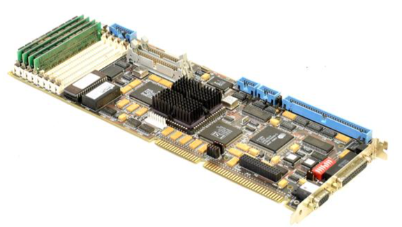
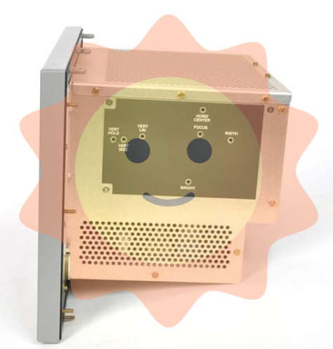
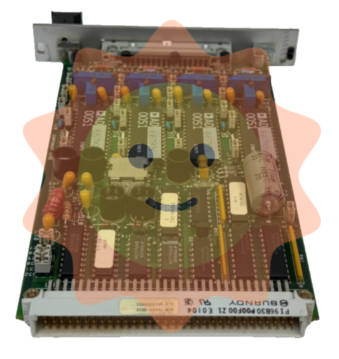
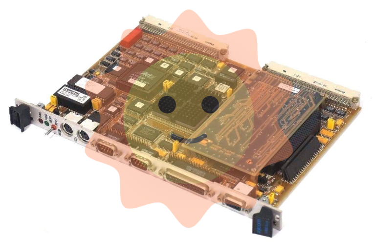
DHR NLS3000 NLC System (Navigation Control System)
Port terminal: positioning and path correction of container cranes (shore bridges, yard bridges);
Industrial scenario: Autonomous navigation of heavy-duty transport vehicles (AGVs), position synchronization of track mounted equipment;
Maritime assistance: guidance for small ships to dock and fixing the position of water operation platforms.
The system supports multi-sensor fusion and can be combined with GPS, LiDAR, encoders and other devices to improve positioning accuracy, in compliance with EU CE certification and industrial equipment electromagnetic compatibility (EMC) standards.
DHR NLS3000 NLC System (Navigation Control System)
Product basic positioning and core functions
1. Product positioning
The NLS3000 NLC System is a high-precision real-time navigation and positioning control system, designed for devices that require precise position monitoring, path planning, and dynamic control. Typical applications include:
Port terminal: positioning and path correction of container cranes (shore bridges, yard bridges);
Industrial scenario: Autonomous navigation of heavy-duty transport vehicles (AGVs), position synchronization of track mounted equipment;
Maritime assistance: guidance for small ships to dock and fixing the position of water operation platforms.
The system supports multi-sensor fusion and can be combined with GPS, LiDAR, encoders and other devices to improve positioning accuracy, in compliance with EU CE certification and industrial equipment electromagnetic compatibility (EMC) standards.
2. Core functions
Specific Capability Value Explanation for Functional Categories
High precision positioning static positioning accuracy ± 5mm (close range laser assistance), dynamic positioning accuracy ± 10mm (speed ≤ 5m/s); Support switching between absolute coordinates (latitude and longitude) and relative coordinates (device local coordinate system) to meet the strict requirements of high-precision operations for position errors, avoiding accidents caused by equipment collisions or positioning deviations
Path planning and control support preset path storage (up to 100 custom paths) and real-time path correction (response delay<100ms); It is possible to set a "prohibited area" (electronic fence), which will automatically slow down/stop when triggered to reduce manual operation intensity, lower the risk of misoperation, and adapt to multi scene operation processes
Data collection and communication: Real time collection of position, velocity, attitude (inclination, heading) data, with a sampling frequency of 100Hz; supports industrial communication protocols such as RS485, EtherNet/IP, Profinet, etc., and can be connected to the upper computer (SCADA system) to achieve remote monitoring of equipment status, facilitating production scheduling and data tracing
Fault diagnosis and alarm built-in sensor fault detection (such as GPS signal loss, LiDAR obstruction), communication interruption alarm; Support fault code storage (up to 50 historical fault records), with sound and light alarm prompts to shorten troubleshooting time and improve system reliability
System composition and hardware architecture
1. List of core components
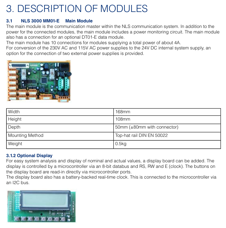
The NLS3000 NLC System is designed with modularity, and the standard configuration includes the following components, which can be added or removed according to the application scenario:
Component Name, Model/Specification, Function and Function
The main controller NLC-3000-MC system core is responsible for data computation, path planning, and device control, with a built-in Linux real-time operating system
Positioning sensor module - GPS receiver: NLC-GPS-01 (supports Beidou/GLONASS dual-mode, positioning update rate 10Hz)
-Lidar: NLC-LIDAR-20 (measuring distance 0.5-20m, accuracy ± 2mm)
-Incremental encoder: NLC-ENC-1024 (resolution 1024 lines/rev, adapted to wheels or tracks) multi-sensor fusion, ensuring positioning accuracy in different environments (such as indoor/obstructed areas with weak GPS signals)
Display and operation unit NLC-HMI-10 10 10 inch touch screen (resolution 1280 × 800), supporting parameter settings, real-time status display, and fault inquiry; Equipped with a physical emergency stop button human-machine interaction interface, convenient for on-site operation and status monitoring
The NLC-IO-16 execution control module has 16 digital inputs/outputs (DI/DO) and 4 analog inputs (AI, 0-10V/4-20mA), used to connect motor drivers, solenoid valves, and other actuators to achieve dynamic control of equipment by the controller (such as speed regulation, steering, braking)
The power module NLC-PWR-24 has an input voltage of 110-240V AC and an output of 24V DC/5A. It is equipped with overvoltage and overcurrent protection to provide stable power supply for various components of the system and is suitable for different on-site power conditions
2. Hardware architecture logic
The system adopts a "layered control" architecture, and the data flow is as follows:
Perception layer: GPS, LiDAR, encoder and other sensors collect position and motion data and transmit it to the main controller;
Control layer: The main controller performs fusion operations on data, generates control instructions based on preset paths and real-time status;
Execution layer: The execution control module receives instructions, drives the motor, brake and other execution mechanisms, and feeds back the execution status to the main controller;
Monitoring layer: HMI and upper computer receive status data sent by the main controller, realizing display, alarm and remote operation.
Key technical parameters
1. Positioning and control performance
Parameter Category Specification Value Remarks
Static positioning accuracy: ± 5mm (laser radar assisted, measurement distance<10m); Dynamic: ± 10mm (speed ≤ 5m/s) accuracy is affected by the environment, such as the laser radar accuracy may drop to ± 5mm in rainy/dusty environments
The speed measurement range is 0-10m/s (effective range of dynamic positioning), and when the speed measurement accuracy exceeds 10m/s by ± 0.1%, it automatically switches to "rough positioning mode"
Attitude measurement inclination range: -15 °~+15 ° (roll/pitch), accuracy ± 0.05 °; Heading angle range: 0-360 °, accuracy ± 0.1 °, requires gyroscope module (optional NLC-GYRO-01)
Response delay sensor data acquisition:<10ms; control command output:<100ms to ensure real-time dynamic control
The path storage capacity is up to 100 paths, and a single path can support up to 1000 coordinate points. Coordinate points can be manually entered through HMI or upper computer
2. Electrical and environmental parameters
Parameter category specification value precautions
Power supply requirements: Main controller: 24V DC ± 10%, maximum current 2A; Sensor module: 12-24V DC ± 10%, total power consumption ≤ 15W, independent power supply circuit is required to avoid sharing power supply with high-power equipment (such as motors)
Communication interface - Industrial Ethernet: EtherNet/IP, Profinet (transmission rate 100Mbps)
-Serial communication: RS485 (baud rate 9600-115200bps, supporting Modbus RTU) communication cable needs to use shielded wire to avoid electromagnetic interference
Protection level main controller/sensor: IP65 (dustproof, waterproof); HMI: IP64 (dustproof, splash proof). It is prohibited to immerse or expose to corrosive environments for a long time (such as maritime scenes with high salt spray concentration that require additional protection)
Environmental adaptability working temperature: -20~+60 ℃; Storage temperature: -40~+85 ℃; Relative humidity: 0%~95% (no condensation). It is recommended to preheat for 30 minutes before starting in a low-temperature environment (<-10 ℃)
EMC compatibility complies with EN 61000-6-2 (industrial environment immunity) and EN 61000-6-3 (residential emission limits). When installing, it is necessary to stay away from strong electromagnetic interference sources (such as frequency converters and high-voltage cables)
Installation and commissioning specifications
1. Pre installation requirements
Environmental inspection: Confirm that the installation location has no strong electromagnetic interference and no severe vibration (vibration frequency ≤ 50Hz, amplitude ≤ 0.5mm); Outdoor installation requires reserved waterproof junction box positions, and sensor installation points should have a wide field of view (GPS receivers should be unobstructed, and LiDAR should avoid obstacles blocking the measurement path).
Qualification requirements: Installation personnel must have industrial automation equipment installation qualifications and be familiar with electrical wiring specifications (such as EN 60204-1); High voltage wiring (such as power module input) must be operated by a certified electrician.
Tools and spare parts: A torque wrench (recommended for fixing sensors with a torque of 2-3Nm), shielded cables (communication cables recommended to use CAT5e or higher specifications), and waterproof sealant (for outdoor wiring protection) need to be prepared.
2. Key points for installing core components
Common Error Avoidance in Component Installation Requirements
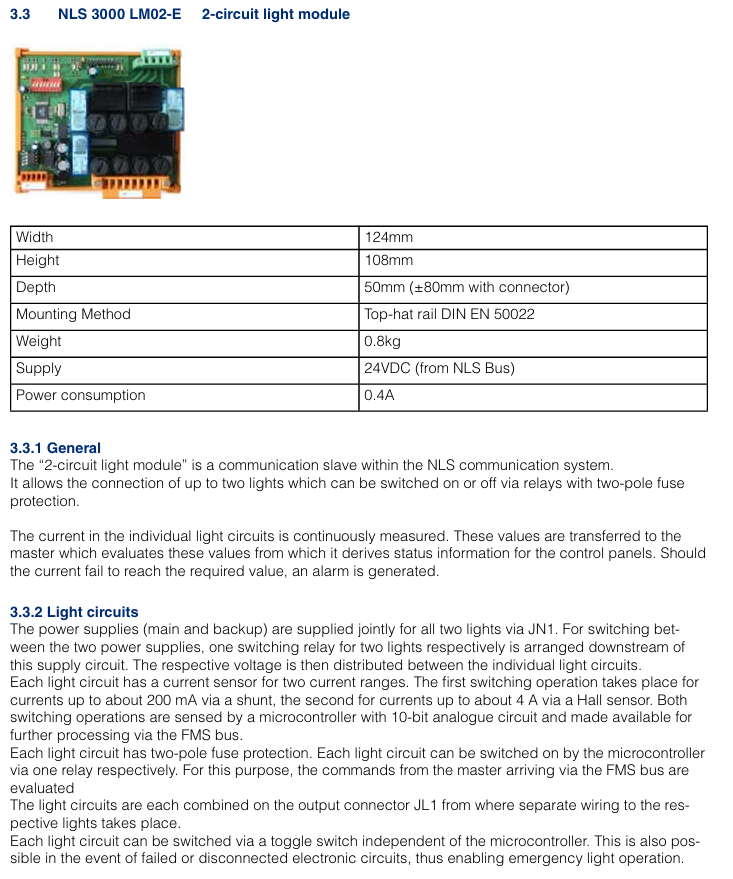
The main controller is installed in the equipment control cabinet, with a distance of ≥ 10cm from the heating element (such as the frequency converter); the fixed bracket needs to be grounded (grounding resistance ≤ 4 Ω) to avoid installation at the bottom (prone to water accumulation) or top (greatly affected by temperature) of the control cabinet
The GPS receiver is installed at the highest point of the device, with a horizontal deviation of ≤ 5 °; Antenna cable length ≤ 10m, avoid bending (bending radius ≥ 50mm). It is prohibited to install it under metal obstructions (such as equipment frames), otherwise it will cause signal loss
The installation height of the laser radar should be level with the measurement target (such as the positioning reflector), and the measurement path should be unobstructed; Avoid installing in areas with severe equipment vibration (such as near motors) at a distance of ≥ 50cm from moving parts, as it may affect measurement accuracy
The HMI is installed within the operator's field of view, with the touch screen at an angle of 30 °~45 ° to the operating table; The emergency stop button should be easily accessible (≤ 50cm from the operating position) and should not be installed within the range of the device's movement trajectory to prevent collision damage
3. Debugging process (key steps)
Check before powering on: Confirm that the wiring is correct (the positive and negative poles of the power supply are not reversed, and the shielding layer of the communication line is grounded), tighten all terminal screws (recommended torque 0.5-1Nm);
System initialization: When the power is turned on, the main controller automatically enters initialization mode (HMI displays "Initiat"), completes self-test after about 30 seconds, and displays "READY" if there are no faults; If the self-test fails, the HMI will display a fault code (such as "E01" indicating abnormal GPS signal), and the corresponding component needs to be checked;
Parameter calibration:
Positioning calibration: Input the device reference coordinates (such as starting position latitude and longitude) through HMI, activate the "automatic calibration" function, and the system will correct the coordinate deviation based on sensor data;
Path input: Manually operate the device to travel along the target path once, and the system automatically records the coordinate points, generates a path, and saves it (which can be named "PATH01", "PATH02", etc.);
Functional testing
Static testing: When the equipment is stationary, observe the position data displayed on the HMI to confirm that the error is within the allowable range (± 5mm);
Dynamic testing: Start the device to travel along the preset path, check if it follows the path, if it automatically stops when the "prohibited area" is triggered, and record the response delay (<100ms required).
Operation and Maintenance Guide
1. Daily operations (HMI interface)
Main interface: Display real-time position (coordinates, distance from target point), speed, attitude data, and system status (normal/alarm);
Path operation: Click on "Path Selection", select the preset path and click "Start", the device will automatically travel along the path; Support "pause" and "emergency stop" (click the HMI emergency stop button or physical emergency stop button);
Parameter settings: Enter the "Settings" interface to modify the positioning accuracy level ("High Precision Mode"/"Normal Mode") and alarm threshold (such as speed upper limit and position deviation upper limit);
Fault inquiry: Enter the "Fault Record" interface, view historical fault codes and occurrence times, click on the code to display the fault cause and solution suggestions.
2. Maintenance cycle and content
Maintenance cycle operation content operation requirements
Check daily whether the HMI display is normal (no splash screen, no errors); Clean the LiDAR lens (wipe with a dust-free cloth); Check the function of the emergency stop button (whether the device stops when pressed) and prohibit wiping the HMI screen with alcohol or corrosive cleaning agents; If there are stubborn stains on the LiDAR lens, special lens paper is required
Check the sensor wiring for looseness every week; Test GPS signal strength (HMI displays' GPS signal ≥ 3 stars' as normal); Check the output voltage of the power module (within the range of 22.8-26.4V DC) and tighten the wiring terminals one by one to avoid omissions; When the GPS signal is weak, it is necessary to check whether the antenna position is obstructed
Monthly calibration of positioning accuracy (activate the "automatic calibration" function); Clean the heat dissipation holes of the main controller (blow off dust with compressed air); Check whether the protective shell is damaged (such as whether the IP65 sealing strip is aged) and calibrate it under the condition of no load on the equipment; Blocked heat dissipation holes can cause the controller to overheat and require thorough cleaning
Replace the laser radar lens protective cover (vulnerable parts) annually; Detecting the grounding status of the shielding layer of communication cables; The overall system function test (including all preset paths) requires the use of DHR original parts for replacing accessories to avoid compatibility issues; The grounding resistance needs to be remeasured to ensure it is ≤ 4 Ω
3. Common fault handling
Possible causes and solutions for the fault phenomenon
HMI displays "GPS signal loss (E01)" GPS antenna obstruction, antenna cable breakage, GPS module malfunction. Check the antenna position and remove the obstruction; Test cable continuity and replace damaged cables; If the fault persists, replace the GPS module
The device deviates from the preset path (deviation>10mm), causing contamination of the LiDAR lens, incorrect encoder parameters, expired path calibration, and cleaning of the LiDAR lens; Re enter the encoder resolution parameter; Activate the 'Auto Calibration' function
System unresponsive (HMI black screen), power module failure, main controller crash, power supply line interruption. Check the output voltage of the power module. If there is no output, replace it; Press and hold the "Reset" button on the main controller for 10 seconds to restart; Check the power supply line and repair the breakpoint
Alarm "Prohibited Area Trigger (E05)": The device accidentally enters the electronic fence, coordinates are set incorrectly, press the emergency stop button, and manually operate the device to exit the prohibited area; Check the coordinates of the prohibited area and correct any incorrect settings
Safety operation instructions
Emergency stop: If there is an abnormality during equipment operation (such as collision risk, sensor failure), the HMI or physical emergency stop button should be immediately pressed to cut off the power supply of the actuator;
Permission management: The system sets three levels of operation permissions (administrator, engineer, operator), and only administrators can modify key parameters (such as positioning accuracy, prohibited areas) to avoid misoperation;
Environmental restrictions: Prohibited from use in flammable and explosive environments (such as oil and gas terminals), unless equipped with explosion-proof components (explosion-proof versions need to be ordered separately); It is prohibited to use in the environment beyond the protection level (such as rainstorm and strong dust);
Training requirements: Operators must undergo official DHR training and pass the assessment, be familiar with the fault handling process, and are prohibited from operating without certification.
- ABB
- General Electric
- EMERSON
- Honeywell
- HIMA
- ALSTOM
- Rolls-Royce
- MOTOROLA
- Rockwell
- Siemens
- Woodward
- YOKOGAWA
- FOXBORO
- KOLLMORGEN
- MOOG
- KB
- YAMAHA
- BENDER
- TEKTRONIX
- Westinghouse
- AMAT
- AB
- XYCOM
- Yaskawa
- B&R
- Schneider
- Kongsberg
- NI
- WATLOW
- ProSoft
- SEW
- ADVANCED
- Reliance
- TRICONEX
- METSO
- MAN
- Advantest
- STUDER
- KONGSBERG
- DANAHER MOTION
- Bently
- Galil
- EATON
- MOLEX
- Triconex
- DEIF
- B&W
- ZYGO
- Aerotech
- DANFOSS
- Beijer
- Moxa
- Rexroth
- Johnson
- WAGO
- TOSHIBA
- BMCM
- SMC
- HITACHI
- HIRSCHMANN
- Application field
- XP POWER
- CTI
- TRICON
- STOBER
- Thinklogical
- Horner Automation
- Meggitt
- Fanuc


