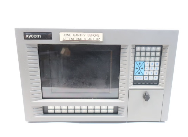
DHR NLS3000 NLC System (Navigation Control System)
Port terminal: positioning and path correction of container cranes (shore bridges, yard bridges);
Industrial scenario: Autonomous navigation of heavy-duty transport vehicles (AGVs), position synchronization of track mounted equipment;
Maritime assistance: guidance for small ships to dock and fixing the position of water operation platforms.
The system supports multi-sensor fusion and can be combined with GPS, LiDAR, encoders and other devices to improve positioning accuracy, in compliance with EU CE certification and industrial equipment electromagnetic compatibility (EMC) standards.
Parameter calibration:
Positioning calibration: Input the device reference coordinates (such as starting position latitude and longitude) through HMI, activate the "automatic calibration" function, and the system will correct the coordinate deviation based on sensor data;
Path input: Manually operate the device to travel along the target path once, and the system automatically records the coordinate points, generates a path, and saves it (which can be named "PATH01", "PATH02", etc.);
Functional testing
Static testing: When the equipment is stationary, observe the position data displayed on the HMI to confirm that the error is within the allowable range (± 5mm);
Dynamic testing: Start the device to travel along the preset path, check if it follows the path, if it automatically stops when the "prohibited area" is triggered, and record the response delay (<100ms required).
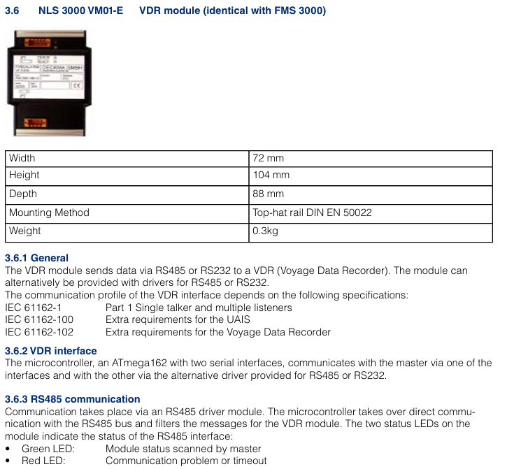
Operation and Maintenance Guide
1. Daily operations (HMI interface)
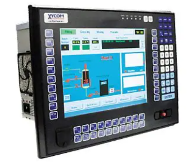
Main interface: Display real-time position (coordinates, distance from target point), speed, attitude data, and system status (normal/alarm);
Path operation: Click on "Path Selection", select the preset path and click "Start", the device will automatically travel along the path; Support "pause" and "emergency stop" (click the HMI emergency stop button or physical emergency stop button);
Parameter settings: Enter the "Settings" interface to modify the positioning accuracy level ("High Precision Mode"/"Normal Mode") and alarm threshold (such as speed upper limit and position deviation upper limit);
Fault inquiry: Enter the "Fault Record" interface, view historical fault codes and occurrence times, click on the code to display the fault cause and solution suggestions.
2. Maintenance cycle and content
Maintenance cycle operation content operation requirements
Check daily whether the HMI display is normal (no splash screen, no errors); Clean the LiDAR lens (wipe with a dust-free cloth); Check the function of the emergency stop button (whether the device stops when pressed) and prohibit wiping the HMI screen with alcohol or corrosive cleaning agents; If there are stubborn stains on the LiDAR lens, special lens paper is required
Check the sensor wiring for looseness every week; Test GPS signal strength (HMI displays' GPS signal ≥ 3 stars' as normal); Check the output voltage of the power module (within the range of 22.8-26.4V DC) and tighten the wiring terminals one by one to avoid omissions; When the GPS signal is weak, it is necessary to check whether the antenna position is obstructed
Monthly calibration of positioning accuracy (activate the "automatic calibration" function); Clean the heat dissipation holes of the main controller (blow off dust with compressed air); Check whether the protective shell is damaged (such as whether the IP65 sealing strip is aged) and calibrate it under the condition of no load on the equipment; Blocked heat dissipation holes can cause the controller to overheat and require thorough cleaning
Replace the laser radar lens protective cover (vulnerable parts) annually; Detecting the grounding status of the shielding layer of communication cables; The overall system function test (including all preset paths) requires the use of DHR original parts for replacing accessories to avoid compatibility issues; The grounding resistance needs to be remeasured to ensure it is ≤ 4 Ω
3. Common fault handling
Possible causes and solutions for the fault phenomenon
HMI displays "GPS signal loss (E01)" GPS antenna obstruction, antenna cable breakage, GPS module malfunction. Check the antenna position and remove the obstruction; Test cable continuity and replace damaged cables; If the fault persists, replace the GPS module
The device deviates from the preset path (deviation>10mm), causing contamination of the LiDAR lens, incorrect encoder parameters, expired path calibration, and cleaning of the LiDAR lens; Re enter the encoder resolution parameter; Activate the 'Auto Calibration' function
System unresponsive (HMI black screen), power module failure, main controller crash, power supply line interruption. Check the output voltage of the power module. If there is no output, replace it; Press and hold the "Reset" button on the main controller for 10 seconds to restart; Check the power supply line and repair the breakpoint
Alarm "Prohibited Area Trigger (E05)": The device accidentally enters the electronic fence, coordinates are set incorrectly, press the emergency stop button, and manually operate the device to exit the prohibited area; Check the coordinates of the prohibited area and correct any incorrect settings
Safety operation instructions
Emergency stop: If there is an abnormality during equipment operation (such as collision risk, sensor failure), the HMI or physical emergency stop button should be immediately pressed to cut off the power supply of the actuator;
Permission management: The system sets three levels of operation permissions (administrator, engineer, operator), and only administrators can modify key parameters (such as positioning accuracy, prohibited areas) to avoid misoperation;
- ABB
- General Electric
- EMERSON
- Honeywell
- HIMA
- ALSTOM
- Rolls-Royce
- MOTOROLA
- Rockwell
- Siemens
- Woodward
- YOKOGAWA
- FOXBORO
- KOLLMORGEN
- MOOG
- KB
- YAMAHA
- BENDER
- TEKTRONIX
- Westinghouse
- AMAT
- AB
- XYCOM
- Yaskawa
- B&R
- Schneider
- Kongsberg
- NI
- WATLOW
- ProSoft
- SEW
- ADVANCED
- Reliance
- TRICONEX
- METSO
- MAN
- Advantest
- STUDER
- KONGSBERG
- DANAHER MOTION
- Bently
- Galil
- EATON
- MOLEX
- Triconex
- DEIF
- B&W
- ZYGO
- Aerotech
- DANFOSS
- Beijer
- Moxa
- Rexroth
- Johnson
- WAGO
- TOSHIBA
- BMCM
- SMC
- HITACHI
- HIRSCHMANN
- Application field
- XP POWER
- CTI
- TRICON
- STOBER
- Thinklogical
- Horner Automation
- Meggitt
- Fanuc


