
OMRON C200H PLC Troubleshooting and Programming Essentials
OMRON C200H PLC Troubleshooting and Programming Essentials: From Memory Architecture to Field Practice
In the development of industrial automation, the OMRON C200H series programmable logic controller (PLC) has become the core of countless factory control systems due to its modular rack structure, rich instruction set, and extremely high reliability. Although the C200H series has gradually withdrawn from the mainstream market, it remains a classic equipment that engineers must face in a large number of old production lines, renovation projects, and emergency repair scenarios. This article will systematically summarize the technical points of C200H (CPU01-E/03-E/11-E) from hardware configuration, memory area, programming skills to fault diagnosis, providing a complete technical manual for on-site maintenance and programming debugging.
System Overview: Rack Structure and Hardware Composition
C200H adopts a rack mounted structure, mainly including:
CPU rack: Install CPU units, power units, and up to 10 I/O units or special I/O units.
Expansion I/O rack: Up to 2 can be connected, and each expansion rack can also install up to 10 units, communicating with the CPU rack through I/O connection cables.
Slave rack: Used in remote I/O systems, controlled by the remote I/O master unit.
The CPU unit model determines the system capability: CPU01-E/03-E does not support SYSMAC LINK/NET Link, while CPU1-E supports these advanced networks. Memory units (RAM/EEPROM/EEPROM) provide program storage (UM) and data storage (DM), with battery powered RAM units able to retain data after power failure.
Memory Region Detailed Explanation: Each Address is the Key to Diagnosis
The memory of C200H is divided into multiple data areas, and understanding the purpose of each area is the foundation for programming and troubleshooting.
1. IR zone (internal relay, letter 000-235)
I/O words: Words 000-029 are assigned to slots on CPU racks and expansion racks, with each slot corresponding to a word. The input bit (such as 00000) reflects the status of the external input signal, and the output bit (such as 00200) controls the external load.
Job position: Words not assigned to I/O (such as 030-235) can be used as internal relays, but their status is lost after power failure.
Special I/O units and slave allocation: Unit numbers 0-9 occupy characters 100-199 (special I/O) or 050-099 (slave).
2. SR area (special relay, letters 236-255)
The SR area contains system flags and control bits, and is the primary source of information for fault diagnosis. Key positions include:
25308: Low battery flag (RAM cell battery voltage drops).
25309: Cycle time error flag (cycle exceeding 100ms).
25310: I/O verification error flag (actual installed unit does not match registered I/O table).
25313: Always ON symbol.
25314: Constant OFF symbol.
25315: First cycle flag (ON only during the first scan cycle after the start of operation).
25400-25502: Clock pulses (1 minute, 0.02 seconds, 0.1 seconds, 0.2 seconds, 1.0 seconds).
25503: Instruction execution error flag (ER), ON when operand exceeds range or indirect DM address does not exist.
25504-25507: Arithmetic flags (CY, GR, EQ, LE) used for comparison and operation instructions.
25215: Output OFF position, set ON to force all output units to power off.
3. AR area (auxiliary relay, letters AR00-AR27)
The multiple digits in the AR area are dedicated and remain in a power-off state. Key position:
AR0000-0009: Special I/O unit or PC Link unit error flag.
AR0014/0015: Remote I/O master station 0/1 error flag.
AR0200-0204: Slave rack 0-4 error flag.
AR2404 (CPU1-E): CPU unit low battery flag.
AR26/27: Maximum/current cycle time (BCD format).
AR18-AR21 (CPU11-E): Calendar/clock data (year, month, day, hour, minute, second, week).
4. DM area (data storage, words DM0000-DM1999)
DM0000-0999: User readable/writable, power off hold.
DM0969-0999 (CPU11-E): Error History Area, capable of storing the last 10 errors (error code, time, date), in conjunction with AR0713-0715 control.
DM1000-1999: Special I/O unit parameter area (read-only, requires programming device to write).
5. HR area (holding relay, HR00-HR99)
Power off hold, used for data that needs to be saved in state.
6. LR area (link relay, LR00-LR63)
Used for data exchange in PC Link or SYSMAC Link systems; Can be used as a workspace when not in use.
7. TC area (timer/counter, TC000-TC511)
Each TC number can be defined as a timer (TIM/TIMH) or a counter (CNT/CNTR). As a bit operand, access completion flag; Accessing the current value (PV) as a word operand.
8. TR area (temporary relay, TR0-TR7)
Only used for temporarily storing execution conditions in branch ladder diagrams and cannot be used across instruction blocks.
Keystone Programming Core: From Basic Instructions to Structured Design
The ladder diagram programming of C200H shares the same logic as relay control, and understanding the scanning mechanism is key.
1. Basic instructions
LD/LD NOT: Read normally open/normally closed contacts to start a logical line.
AND/AND NOT: Connect normally open/normally closed contacts in series.
OR/OR NOT: Parallel normally open/normally closed contacts.
OUT/OUT NOT: Output coil.
AND LD/OR LD: Series/parallel logic block.
2. Timers and counters
TIM: 0.1 second unit, set value 0-99.9 seconds. When the execution condition is ON, subtract 1 and complete the flag ON when it reaches zero.
TIMH (15): 0.01 second high-precision timer (note the impact of cycle time).
CNT: Countdown counter, counting input decreases by 1 every OFF → ON, reset input returns to set value when ON.
CNTR (12): Reversible counter, with up/down input controlled separately, cycle counting (0 → SV becomes 0 and sets completion flag, SV → 0 becomes SV and sets flag).
Important limitation: Each TC number can only be defined once. The timer will reset in the interlock zone (IL-ILC) or when power is off, while the counter will not.
3. Interlocking and jumping
IL (02)/ILC (03): Interlock. When IL executes the condition OFF, the middle output coil is all OFF, the timer is reset, and the counter/hold bit/KEEP bit remains in the state.
JMP (04)/JME (05): Jump. When the jump number is 01-99, the skipped instruction is not executed and the state is maintained; Skip to the next JME00 when the jump number is 00, but the search will cause a slight increase in the cycle.
Step instruction (STEP (08)/SNXT (09))
Used to implement sequential control. Each step is defined by a control bit, and during step execution, all internal outputs and timers are reset, but counters, KEEP bits, and shift registers remain. After completing the step, it will automatically reset to the previous step and start the next step. Supports three structures: sequential, branching, and parallel.
5. Subroutines and Interrupts (CPU1-E)
SBS (91) calls subroutines (SBN (92)/RET (93)), which can be nested up to 16 layers.
INT (89) controls scheduling interrupts and sets the time interval (0.01-99.99 seconds) for timed interrupts (subroutine 99).
Programming console operation: a powerful tool for on-site debugging
The C200H programming console is the most commonly used debugging tool on site, and the following are the key operating procedures:
1. Start preparation
After power on, it displays "Password!". Press CLR → MONTR → CLR to enter.
Press SHIFT+1 to turn on/off the button beep sound (BZ displayed).
2. Memory clearing
In Program mode, press CLR → PLAY/SET → NOT → REC/RESET → MONTR to clear all memory. You can choose to retain HR/AR, CNT, or DM regions.
3. I/O table registration
Register the current actual I/O configuration by pressing CLR → FUN → SHIFT → CH → CHG → 97 → 13 → WHITE. After registration, when the actual unit does not match the registry, it will report "I/O VER ERR".
4. Program input
Set address (e.g. 00000) → Enter command (e.g. LD 00000) → Press Write → Enter operand (e.g. 00001) → Press Write.
Function command: Press FUN+Function code+Write. Add NOT input differential command (@).
5. Program inspection
Press CLR → SRCH, select check level (0: all errors; 1: Class A/B; 2: Only Class A). The check will stop at the first error, press SRCH to continue.
6. Monitoring and Enforcement
Bit/word monitoring: After entering the address, press MONTR. It can monitor 6 addresses simultaneously and display cursor movement.
Force Set/Reset: In monitoring mode, press PLAY/SET to temporarily force ON, and press REC/RESET to force OFF. Press SHIFT+PLAY/SET to lock the force (display S or R), press NOT to cancel.
Force clear all: Press CLR → PLAY/SET → REC/RESET → NOT.
Modify data: Press CHG on the monitoring word, enter the new value, and then press WRITE.
7. Tape backup
Save program: Press EXT → 0 → Write to enter file number → Start address → End address → Start the recorder → Press SHIFT+REC/RESET within 5 seconds.
Recovery program: Similar, press SHIFT+PLAY/SET.
Troubleshooting: A systematic approach from indicator lights to error codes
C200H provides self diagnostic function to quickly locate problems through CPU panel indicator lights and SR/AR area markings.
1. Meaning of CPU indicator light
Meaning of indicator light status
POWER is on and the power supply is normal
RUN lights up and the program is running
ALARM/ERROR flashing non fatal errors (such as I/O validation errors, low battery, etc.) FAL)
ALARM/ERROR constantly on for fatal errors (such as CPU exception, memory error, FALS), RUN light off, output completely disconnected
OUT INHIBIT: SR25215 (output OFF position) is ON, and all outputs are forcibly turned off
2. Common error messages and countermeasures
Initialization error (RUN does not light up when powered on)
Reasons for the message and countermeasures
WAITING FOR START INPUT CPU power supply unit startup input terminal not short circuited, short circuited startup terminal
WAITING FOR REMOTE I/O Remote I/O Power or Terminal Resistance Problem Check Slave Power and Terminal Resistance
Non fatal error (ALARM flashing, running continues)
Reason and countermeasures for message FAL number
FAL Error 01-99 program executed FAL (06) to check user-defined FAL conditions
Cycle Time Overrun F8: If the cycle time exceeds 100ms, optimize the program or reduce the scanning load
I/O VER ERR E7: The I/O table does not match the actual unit. Perform I/O table verification and re register
Remote I/O ERROR B0/B1 communication fault check for the line between the master and slave stations
Special I/O Error D0 Special I/O Unit Error Check Unit Number (AR00), Reset (AR01)
BATTERY ERROR F7 Backup battery voltage low Replace battery (C200H-BAT09)
Fatal error (ALARM constantly on, RUN off)
Reason and countermeasures for message FAL number
CPU ERROR: No watchdog timeout (default 130ms). Check if the program is in a dead loop, or use WDT (94) to extend it
Memory Error F1: Check for missing, checksum errors, or illegal instructions in the memory unit installation and execute program checks
NO END INST F0 program does not have END (01). Add END (01) at the end of the program
I/O BUS ERROR C0-C2: Check for bus faults between CPU and I/O unit. Connect the rack cable and tighten the unit
TOO MANY UNITS E1 Special I/O Unit Number Duplicate, or SYSMAC LINK/NET Link Operation Level Conflict Check Unit Number Setting (0-9 Unique), Check Operation Level
FALS ERROR 01-99/9F program has executed FALS (07) or watchdog timeout. Check according to the FAL number; 9F indicates a period exceeding 130ms
3. Error History (CPU11-E)
DM0969-DM0999 stores the last 10 error records (error code, time, date). Enable AR0715 (Error History Enable Bit), and AR0713 determines whether to overwrite it. It can be reset through AR0714.
4. Application of arithmetic flags in programs
Compare the results of instruction CMP (20) and output them to GR (25505), EQ (25506), and LE (25507).
These flags must be used immediately after CMP, as END (01) will clear them.
Example: Compare HR09 and IR010, output according to different result settings.
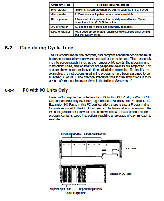
Cycle time and I/O response time: key to timing sensitive applications
The cycle time of C200H includes: supervised processing+program execution+I/O refresh+peripheral services+link unit services (if any). Typical values: The supervision time of CPU01-E/03-E is 2.6ms, with a refresh time of 70 μ s for each input word and 40 μ s for each output word.
When the cycle time exceeds 100ms, SR25309 ON, And the 0.1 second clock pulse may not be accurate.
The maximum cycle time is stored in AR26, and the current cycle is in AR27.
Use SCAN (18) to set the minimum cycle time (CPU1-E).
The I/O response time (from input signal change to output action) depends on the input ON delay+cycle time x 1 or 2+output ON delay. If the input arrives before I/O refresh, the response is the fastest (one cycle); If it arrives after refreshing, it will take two cycles.
- ABB
- General Electric
- EMERSON
- Honeywell
- HIMA
- ALSTOM
- Rolls-Royce
- MOTOROLA
- Rockwell
- Siemens
- Woodward
- YOKOGAWA
- FOXBORO
- KOLLMORGEN
- MOOG
- KB
- YAMAHA
- BENDER
- TEKTRONIX
- Westinghouse
- AMAT
- AB
- XYCOM
- Yaskawa
- B&R
- Schneider
- Kongsberg
- NI
- WATLOW
- ProSoft
- SEW
- ADVANCED
- Reliance
- TRICONEX
- METSO
- MAN
- Advantest
- STUDER
- KONGSBERG
- DANAHER MOTION
- Bently
- Galil
- EATON
- MOLEX
- DEIF
- B&W
- ZYGO
- Aerotech
- DANFOSS
- Beijer
- Moxa
- Rexroth
- Johnson
- WAGO
- TOSHIBA
- BMCM
- SMC
- HITACHI
- HIRSCHMANN
- Application field
- XP POWER
- CTI
- TRICON
- STOBER
- Thinklogical
- Horner Automation
- Meggitt
- Fanuc
- Baldor
- SHINKAWA
- Other Brands
- UniOP
- KUKA
- Iba
-
 Omron IDSC-C1DR-A-E ID Controller PLC Unit
 -
 Omron F350-L100E OVL Image Processing Unit Vision System PLC
 -
 Omron CJ1W-F159 Load Cell Interface Weighing Module
 -
 Bticino MA250 T7314A250 Megatiker PLC Module
 -
 Mitsubishi AJ71QLP21G GI Fiber Optic Network Module
 -
 Omron R88D-HS10 Servo Drive DC Type
 -
 Omron FZ3-L355 Vision Sensor Controller
 -
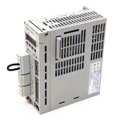
 Omron C200H-CPU23-E CPU Unit PLC
 -
 Moeller UNIOP MI4-110-KG2 Text Display HMI
 -
 KEB COMBIVERT F5 07.F5.B1B-3B0A Inverter
 -
 Toshiba VFS15-4037PL-W Variable Frequency Drive
 -
 Omron CS1W-SCU31-V1 Serial Communication Unit
 -
 LSIS SV055iG5A-4 AC Drive 5.5kW
 -
Omron CJ1W-F159 Loadcell Interface Unit
-
 Omron CQM1-TC001 Temperature Control Module
 -
 Mitsubishi FX5-SF-MU4T5 Safety Module
 -
 Omron C1000H-CPU01-EV1 CPU Unit
 -
 Yaskawa SGDV-2R8A11A Servo Drive 400V
 -
 Omron 3G3HV-A4055-CUE VFD 5.5kW
 -
 Omron F160-C15E Vision Sensor Controller
 -
 Schneider ELAU PMC-2 Servo Drive 2.2kW
 -
 Omron CQM1-TC102 Temperature Control Unit
 -
 Omron CS1G-CPU65-EV1 CPU Unit CS1 Series
 -
 Omron CJ1H-CPU66H CPU Unit High Performance
 -
 Saia PCD4.H320 Analog Input Module
 -
 Omron NX-EIC202 EtherNet/IP Coupler Unit
 -
 Omron R88M-H75030 Servo Motor OMNUC Series 750W
 -
 Omron F500-VS Vision Sensor F500 Series Machine Vision
 -
 Omron R88S-H306G Power Unit for Servo Motor OMNUC Series
 -
 Banner Q45ULIU64ACR Ultrasonic Sensor Q45U Series Proximity Mode
 -
 Allen Bradley 1756-IRT8I RTD Thermocouple Input Module ControlLogix
 -
 Siemens Sinumerik 840D SL NCU 720.3B with PLC 317-3 PN DP
 -
 Kollmorgen SERVOSTAR J-06 Servo Drive Danaher Motion
 -
 Omron NX-ECC202 EtherCAT Coupler Unit NX Series
 -
 OMRON CS1W-SCU31-V1 Serial Unit
 -
 Beckhoff CX5020-0110 Embedded PC PLC
 -
 Omron CJ1M-CPU13-ETN CPU Unit Ethernet
 -
 Omron C60H-C1DR-DE-V1 PLC Controller
 -
Omron CJ1W-PTS51 Thermocouple Input Unit
-
 Omron CJ1W-DA021 Analog Output Module 2 Ch
 -
 Omron CS1W-MAD44 Analog I/O Module
 -
 Omron C500-PRW05-V1 PROM Writer
 -
 Omron CJ1G-CPU45H Loop Control CPU Unit
 -
 ABB PSTX570-600-70 Soft Starter 570A
 -
 PTF Electronic SCR W1Z Power Controller 1150mm
 -
 Omron C500-CT012 High Speed Counter Unit
 -
 NBC Electronics MOD.ES 3 Ton Load Cell
 -
 DeltaOmega XML2 0060 45 4 S A Servo
 -
 REM EC235 Counter Module
 -
 Motor Power SKA DDR 148.30.8.19 Torque Motor
 -
 Delta Tau 4-Axis Interface PLC
 -
 Yokogawa PC10020 AA00 L1Z002 Position Controller
 -
 OMRON C60H-C5DR-DE-V1 PLC
 -
 Burgess PCD4.H320 Motion Control PLC
 -
 Parker SMB14245155242ID644 Servo Motor
 -
 Baumuller PLC-01 BMC-M-PLC-01-11-02 PLC
 -
 Omron CPM2B-32C2D1T-D12 PLC Compact Controller
 -
 Ansaldo SVTS076FBNF Industrial Drive 76KVA
 -
 Omron C500-PRW06 PROM Writer Programmer
 -
 Mitsubishi FX0N-24MR-ES PLC Compact Controller
 -
 Omron R88D-HS22 Servo Drive OMNUC H Series
 -
 Omron CJ1M-CPU11-ETN CPU Unit PLC
 -
 Bosch Rexroth 109129B051 HCP08 PLC Board
 -
 Landis Gyr PCD4.M125 PLC CPU Module
 -
 Nidec SP4202 Variable Frequency Drive 22kW
 -
 Puls QS40.241 Power Supply 40A 24VDC
 -
 Eaton XV-102-B6-35MQR-10-PLC Touch Panel
 -
 Omron ZFX-C15 Vision Sensor Controller
 -
 Kyosan PHS-4C-AN1 Servo Control Power Supply
 -
 Omron NX-ECC201 EtherCAT Coupler Unit
 -
 Omron C20-CPU83E CPU Unit 3G2C7-CPU83E
 -
 Omron FZ-SQ100F Vision Sensor Camera
 -
 Siemens 6SL3352-6BE00-0AA1 Power Supply Board
 -
 ABB AO815 3BSE052605R1 Analog Output Module
 -
 Siemens C98043-A1200-L Control Card
 -
 Allen-Bradley 1336-BDB-SP72D Gate Drive PCB
 -
 ST2000 34 Algorab Graphic PLC Terminal
 -
 OMRON C200HW-PRM21 Profibus DP Module
 -
 Siemens 2020964-001 DPM Base Board
 -
 OMRON CJ1W-V600C11 ID Controller Unit
 -
 Telemecanique TSX7 Series PLC Module
 -
 Okuma 1911-2861-0236049 Graphic Card Module
 -
 Parker HPD2S2N Servo Driver
 -
 OMRON FQ2-D31 Touch Finder Vision Sensor
 -
 OMRON C500-LK007 Host Link Unit
 -
 OMRON CJ1W-SCU32 Serial Communication Unit
 -
 Edwards C41901000 24V Solenoid Valve
 -
 ABB Procontic CS31 07 KR 91 PLC Controller
 -
 Siemens 7KG7750-0AA01-0AA0 Power Meter
 -
 Demag NC4K Compact PLC Controller
 -
 ABB SAPC 35 PAC/PP8482 Pulse Amplifier Board
 -
 Yaskawa SGMGH-09DCA6H-OY Servo Motor 850W
 -
 Saia PCD4.M445 Processor Module PLC
 -
 Yaskawa SGDH-04AE Servo Drive 400W 200V
 -
 Omron H8PR-24 Cam Positioner
 -
 Omron F150-C10E-2 Vision Sensor
 -
 OMRON 3G3MX2-A4015-E Inverter
 -
 Pro face GP577R-TC11 HMI
 -
 Pro face GP477R-EG11 HMI
 -
 ABB Pluto S20 V2 CFS Safety PLC
 -
 Siemens A5E00825002 IGD Board
 -
 Sakae SH40JHK-ZU-3S1R3G-10621B Joystick
 -
 Siemens 3RK1105-1AE04-0CA0 Safety Relay
 -
 Allen Bradley 1775-MEF Memory Module
 -
 OMRON CS1H-CPU63-H PLC CPU Unit
 -
 OMRON F150-C15E-3 Vision Sensor
 -
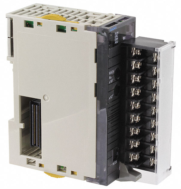 Omron CJ1W-DA041 Analog Output Module
 -
 Saia PCD4.M440 PLC Module PCD4.M44
 -
 Steiel S595 PH Industrial Controller
 -
 VT650 PC Windows 2000 HMI Panel PC
 -
 Omron C200H-AD003 Analog Input Module
 -
 Omron CJ1W-V600C11 ID Sensor Unit
 -
 Coherent 250W Laser Adjustable Lens Head
 -
 Omron CQM1-AD042 Analog Input Module
 -
 SICK XKS09-HTBM-S02 Wire Draw Absolute Encoder
 -
 Omron 3F88L-P3A-E Cam Positioner PLC
 -
 OMRON R88M-H1K130 Servo Motor
 -
 SIEMENS 6ES7 331-7KB01-0AB0 SM331 Analog Input Module
 -
 LANDIS PCD4.M110 Processor Module
 -
 OMRON NT631C-ST151-EV2 HMI Touch Screen
 -
 TE.CO Grey Cable TFX 4G 1.5 ST 564mt UNEL Grey
 -
 OMRON R88D-H310G Servo Drive
 -
 ABB SACE SM3 630 630A PLC Switch
 -
 OMRON DRT2-AD04H Analog Input Terminal
 -
 OMRON FZ-SQ100F Vision Sensor
 -
 OMRON CP1E-NA20DT1-D CPU Unit PLC
 -
 Omron ZFX-C25-CD Vision Controller PNP 2-Camera
 -
 Omron ZFV-NX1 Smart Vision Sensor CCD Camera


