
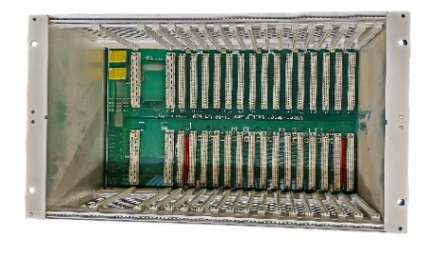
Rockwell Automation SLC 500 Series Programmable Logic Controller
Rockwell Automation SLC 500 Series Programmable Logic Controller
Introduction: The classic cornerstone of industrial automation
In the field of industrial automation, the Allen Bradley SLC 500 series programmable logic controller (PLC) occupies an indelible historical position. As a key bridge connecting early relay control systems with modern complex networked control, SLC 500 not only demonstrates extremely high reliability in hardware, but its instruction set system also lays the foundation for programming concepts on subsequent platforms such as ControlLogix. This article is based on the 1747-RM001G-EN-P reference manual and aims to provide an in-depth analysis of the core instruction system of SLC 500, from the underlying data architecture to advanced closed-loop control, providing automation engineers with a highly practical and valuable professional guide.
Chapter 1: The underlying logic of processor file architecture
To master SLC 500 programming, the primary task is to understand its memory architecture. The user memory of SLC 500 is strictly divided into two categories: data files and program files. This structured design ensures efficient addressing and secure isolation of data.
1. Fine division of data files
The data file numbers range from 0 to 255, and the system assigns specific file types by default:
I/O Image Area (File 0&1): File 0 is the output image, and File 1 is the input image. Its addressing format strictly follows the structure of O: e.s/b or I: e.s/b. Among them, e represents the physical slot number, s represents the word address (for modules with more than 16 I/O points), and b represents the bit number. This method of directly binding physical location with logical address greatly facilitates on-site wiring verification.
Status file (File 2, S:): This is the "black box" of the processor, which records key information such as system clock, error codes, communication status, etc. For example, S: 1/15 is the first scan bit, commonly used for system initialization; S: 5/0 is a math overflow trap bit, if not reset in time, it will cause the processor to crash.
Data storage area (File 3-8): The default configuration includes bit files (B3), timers (T4), counters (C5), controls (R6), integers (N7), and floating-point numbers (F8). It is particularly noteworthy that the timer and counter are a 3-bit element structure, containing control words, preset values (PRE), and cumulative values (ACC), respectively. This composite structure requires special attention to the difference between word addressing and bit addressing during programming.
2. Hierarchical management of program files
File 2 is the main program, and files 3 to 255 are subroutines. Through this division, engineers can decouple complex process logic into independent modules, enabling code reuse and maintenance.
Chapter 2: Fine Control Mechanism of Basic Instructions
The basic instructions form the backbone of ladder logic, but in SLC 500, seemingly simple instructions hide strict timing and state preservation mechanisms.
1. The combination of virtual and real logic
XIC (check for closure) and XIO (check for disconnection) are not simply reading physical states, but checking for "logic 1" or "logic 0" in the data table. This means that if a physically disconnected button (input 0) is latched (OTL) to 1 in the program, the XIC instruction will still be judged as true. OTE (Output Excitation) is non hold type, and its state will be reset if it is in the MCR (Main Control Reset) disabled area or power off; OTL (latch) and OTU (unlock) have retention characteristics, which require extreme caution in safety circuit design.
2. Three forms of timers
TON (Connection Delay): The most commonly used timer that starts counting when the step condition is true, and when the preset value is reached, the Done bit (DN) is placed. When the condition becomes false, it is immediately reset.
TOF (disconnection delay): Timing starts when the step conditions become false. Engineering Pit Avoidance Guide: Never use RES (Reset) command to reset TOF, as RES will clear all status bits, causing timing confusion.
RTO (Hold Timer): Even if the step conditions become false or power is lost (with battery backup), the accumulated value will be maintained. It must be manually reset through the RES command, which is commonly used to record the accumulated running time of the device.
3. Counter and high-speed pulse processing
CTU (up counting) and CTD (down counting) are triggered along the transition edge from false to true in the cascade. When the count value exceeds+32767, the overflow bit (OV) is set and the value becomes -32768, which is a characteristic of signed integer complement. For the fixed SLC 500, the HSC (high-speed counter) instruction allows direct processing of hardware pulses up to 8kHz, but this requires physically disconnecting the J2 jumper inside the controller, configuring I: 0/0 as high-speed input mode, and asynchronous delay between its software accumulation value and hardware count value.
Chapter 3: Advanced Applications of Data Operations and Comparisons
In modern control systems, simple traffic light logic is no longer sufficient, and data processing and computation have become the core.
1. Game between mathematical instructions and state bits
When executing instructions such as ADD, SUB, MUL, DIV, etc., the processor updates the arithmetic state file (S: 0). Among them, the handling of overflow bits (S: 0/1, i.e. V bits) is a major disaster area in programming. If the result of the operation exceeds the range of 16 signed integers (-32768 to 32767), the V position is taken. If S: 5/0 (minor error bit) is still 1 at the end of the scanning cycle, the processor will report an error and shut down. Therefore, the professional programming habit is to immediately use OTU instructions to reset S: 5/0 after mathematical operations, or use S: 2/14 (mathematical overflow selection bit) to implement truncation processing for 32-bit addition and subtraction operations.
2. Block transfer and data scaling
In analog processing, SCP (with parameter scaling) instruction is a powerful tool. It directly maps the raw ADC values from 0-32767 to engineering units (such as 0-100.0 PSI) based on the linear equation y=mx+b operation. In contrast, the SCL (data scaling) instruction uses the form of Rate/10000, which has a complex calculation process and is prone to overflow in intermediate steps. SCP is more recommended in modern programming.
3. Logical traps in comparing instructions
The LIM (Limit Test) instruction has a unique inversion logic: when the low limit is greater than the high limit (such as low limit=10, high limit=5), the instruction outputs false when the test value is between 5 and 10, and true when it is less than 5 or greater than 10. Although this design is clever, it is easily overlooked during code review, leading to logical errors.
Chapter 4: Black Technologies for File Operations and Stack Management
SLC 500 provides efficient file instructions for processing large amounts of data.
1. In depth analysis of COP and FLL
COP (File Copy) and FLL (File Fill) are powerful tools for handling arrays. The key lies in the explanation of the "length" parameter: it is measured in units of the elements of the target file. For example, copying an integer file (1 word/element) to a timer file (3 words/element), if the length is set to 10, the actual copied data amount is 30 words. This mechanism is very practical in data type conversion, but it is also prone to causing memory out of bounds errors.
2. Asynchronous coordination between FIFO and LIFO
FIFO (First In First Out) and LIFO (Last In First Out) instructions manage the stack through the control element (R6). FFL (load) writes data at the position pointer and increments the pointer, while FFU (unload) reads data from position 0 and moves the entire array forward. In a multitasking environment, it is necessary to ensure strict timing matching between loading and unloading, otherwise it may lead to data misalignment. The DN (full) and EM (empty) bits in the control word are key monitoring points for achieving production cycle synchronization.
Chapter 5: Program Flow Control and System Architecture Optimization
A good program architecture is not only related to execution efficiency, but also to the maintainability of the system.
1. Nested risk of subroutine calls
JSR (jump subroutine) allows up to 8 levels of nesting (only 3 levels are allowed within interrupt subroutines such as STI or DII). Although nesting can save code, excessive nesting can lead to stack overflow risks. More importantly, if the output coil (OTE) is located in a subroutine, the output will maintain its final state between two calls, and this "implicit memory" is often the culprit of on-site faults.
2. Boundary trap of MCR (Master Reset)
MCR is used to isolate equipment maintenance areas or formula switching areas. However, it is strictly prohibited to jump (JMP) into the MCR area. Because once jumped in, the processor may misjudge the state of the MCR starting step, which may cause accidental excitation of the output that should have been isolated, resulting in serious safety accidents. In addition, MCR is not a hardware power outage, and the behavior of the timer in the MCR disabled area (such as TOF continuing to count) is different from physical power outage.
3. Precise Strike of Interruption Mechanism
For SLC 5/03 and above processors, STI (optional timed interrupt) and DII (discrete input interrupt) allow breaking the constraints of sequential scanning. Putting PID operations or high-speed encoder readings into STI subroutines can ensure absolute constant control cycles. However, it should be noted that interrupt service programs (ISR) should be as short as possible to avoid blocking the main logic.
Chapter 6: Practical Application of Special Instructions in Complex Processes
1. Shift Register (BSR/BSR)
In assembly line tracking, the BSL instruction is preferred. It shifts the entire bit array to the left, with new data entering from the Source bit and overflow bits entering the UL (unload) bit. By monitoring the UL position, the moment when the product reaches a specific workstation can be accurately captured without the need to write lengthy state machine code.
2. Sequencer (SQO/SQC)
SQO (Sequential Output) traverses pre-set data files through step pointers and outputs different bit patterns to physical ports using masks. This is more intuitive than complex ladder diagram interlocking logic. SQC (Sequential Comparison) is commonly used for step confirmation, which compares the input state with the reference mask and uses the FD (Find) bit to determine whether the current step is completed.
3. Bottom layer handshake for block transfer (BTR/BTW)
When communicating with special I/O modules such as servo drives and smart meters, BTR/BTW is the only bridge. It asynchronously exchanges data with scanners (such as 1747-SN) through M0/M1 files as buffers. The handshake timing in the control block is extremely strict: EN (enable) is set by the program, ST (start) and DN (finish) are set by the hardware scanner, and the program must immediately clear EN after detecting DN, otherwise the next transmission will be blocked.
Chapter 7: The Art of PID Closed Loop Control
The PID instruction is the most complex monolithic instruction in SLC 500, with its 23 word control block hiding a lot of control details.
1. Independent integer algorithm
Unlike PLC-5 or ControlLogix which use floating-point PID, the PID of SLC 500 is completely integer operated, and the internal variable range is forcibly limited to 0-16383. This means that all analog inputs (such as 3277-16384 corresponding to 4-20mA) must first be scaled to this range through SCL or SCP commands.
2. Anti integral saturation and hand automatic undisturbed switching
When the output is limited, if no measures are taken, the integral term will accumulate infinitely, resulting in the output still being unable to fall back after the deviation is eliminated (i.e. integral saturation). The SLC 500 achieves hardware level anti saturation through OL (output limiting enable) and CL bits. At the same time, in manual mode (AM=1), the algorithm will automatically adjust the integral sum to ensure that when switching back from manual to automatic, the control variable (CV) will not undergo step jumps, achieving true disturbance free switching.
3. Selection of Timing Mode and STI Mode
Although PID supports internal scheduled updates, this mode is not recommended in circuits with strict requirements due to the jitter of the scanning cycle. The best practice is to place the PID into an STI subroutine that strictly matches the cycle with the 'Loop Update' parameter to obtain a deterministic control cycle.
Chapter 8: Fault Diagnosis and System Robustness Design
1. Deep mining of status files
S: The six characters contain the code for the last major malfunction. For example, error code 0020 usually points to an unprocessed mathematical overflow; Error code 0036 indicates that the PID parameter is out of bounds. By using the user fault subroutine (file 3 or specified file), it is possible to record the fault context before the processor crashes, and even attempt a soft reset for non fatal errors.
2. Communication diagnosis of I/O module
For remote I/O (RIO) networks, use G files (dedicated I/O module data) to monitor the module's network access and disconnection status. For local expansion racks, the disconnection situation is determined by checking the specific position of the input image (if supported by the module), rather than relying on simple cascade logic.
3. Defense design for power failure
Although SLC 500 has power failure protection function, the worst-case scenario should be assumed during design. Use S: 1/15 (first scan position) to forcibly initialize key control positions (such as hydraulic start permission position, safety door status) during each power on, to avoid dangerous actions after restart due to data flipping at the moment of power failure.
- ABB
- General Electric
- EMERSON
- Honeywell
- HIMA
- ALSTOM
- Rolls-Royce
- MOTOROLA
- Rockwell
- Siemens
- Woodward
- YOKOGAWA
- FOXBORO
- KOLLMORGEN
- MOOG
- KB
- YAMAHA
- BENDER
- TEKTRONIX
- Westinghouse
- AMAT
- AB
- XYCOM
- Yaskawa
- B&R
- Schneider
- Kongsberg
- NI
- WATLOW
- ProSoft
- SEW
- ADVANCED
- Reliance
- TRICONEX
- METSO
- MAN
- Advantest
- STUDER
- KONGSBERG
- DANAHER MOTION
- Bently
- Galil
- EATON
- MOLEX
- DEIF
- B&W
- ZYGO
- Aerotech
- DANFOSS
- Beijer
- Moxa
- Rexroth
- Johnson
- WAGO
- TOSHIBA
- BMCM
- SMC
- HITACHI
- HIRSCHMANN
- Application field
- XP POWER
- CTI
- TRICON
- STOBER
- Thinklogical
- Horner Automation
- Meggitt
- Fanuc
- Baldor
- SHINKAWA
- Other Brands
- UniOP
- KUKA
- Iba
-
 Tokyo FAO111A Industrial Control Module
 -
 Toshiba AFX-90L-RH XRF Analyzer Tube
 -
 Toshiba GBU648E S Bridge Rectifier Module
 -
 Toshiba TCPSV Servo CPU Module J7000 Series
 -
 Toshiba HFAS11S Servo Drive Module
 -
 TOYOA MC256-C Servo Controller Module
 -
 TEL TVB6002-1 1308-644857-12 RF Control Interface
 -
 TEL TVB3101-1 1381-644957-16 RF Module Specs
 -
 Telemecanique BW06 Industrial Limit Switch
 -
 Teradyne A1004-00003 398-723-00 Interface Board
 -
 Leybold THERMOVAC TR301 15740 Vacuum Transmitter
 -
 TOKYO TK6132A8 Industrial Control Module
 -
 TOYOPUC OUT-16 THK-2791 PLC Output Module
 -
 TPC FFLC6-3483-B Industrial Interface
 -
 TPC FPX86-9345-B Pneumatic Control
 -
 TR Electronic ZE65M Absolute Encoder
 -
 TRACO POWER T1032-07C Industrial DC/DC Converter
 -
 TRACO POWER T1023-07C High-Efficiency Power Module
 -
 Trafo SLOV4.6/5.3 3BHL000734P0003 Isolation Transformer
 -
 Trafotek CHK0520 Current Transformer
 -
 Transcend 128MB PC133 SDRAM Memory Module
 -
 Transition Networks J/E-CF-02 Media Converter
 -
 TRASFOR DRMBW20/L 3BHB009181P0001 Drive Power Module
 -
 TRASFOR DRMBW30/L 3BHB009182P0001 Rectifier Transformer Module
 -
 Trenew VME-GrundSystem VMEbus Chassis
 -
 Trumpf TE 1605341 VER02 Circuit Board
 -
 Trumpf MBE3-50 Laser Control Electronics
 -
 TSC Carat 1008FC Industrial Power Module
 -
 Turck FDNL-L0800-T DeviceNet Fieldbus I/O Module
 -
 Turck MK35-LI-EX0 Intrinsically Safe Isolation Amplifier
 -
 Turck MK33-LI-EX0 Intrinsically Safe Inductive Sensor
 -
 Turck JBBS-49-E413/3 PROFIBUS DP Junction Box
 -
 Turck BL20-16DI-24VDC-P Digital Input Module
 -
 TWUNCOM J592S-450550 Dual Serial I/O Module
 -
 TE Connectivity KUEP-11D15-24 General Purpose Relay
 -
 UE LDP1WC 250P-16 Low Differential Pressure Switch
 -
 UniOP ETT-VGA-0045 Operator Panel
 -
 UniOP TCM08A Communication Module
 -
 UniOP ETT-VGA HMI Terminal Technical Specifications
 -
 Vacon PC00459G CM210901 Control Board
 -
 Valmet CXW D201435L Controller
 -
 Valmet A413305 I/O Module
 -
 Valmet A413280 DNA System Processor Module
 -
 Valmet CPR1 A413280 Processor Module
 -
 Valmet A413295 Valve Controller Module
 -
 Valmet A413285 Industrial Control Module
 -
 Valmet A413052 8-Channel Analog Output Module
 -
 Valmet A413045 Industrial Control CPU Module
 -
 VIBRO-METER 200-595-002-011 Interface Module
 -
 VIBRO-METER 573-935-202C Monitoring Module
 -
 VIBRO-METER VM600 MPC4 200-510-111-034 Monitoring Card
 -
 VIBRO-METER MPC4 200-510-076-115 Protection Monitoring Card
 -
 VIBRO-METER CMC16 200-530-022-014 Communication Module
 -
 VIBRO-METER MPC4 200-510-111-035 Machinery Protection Card
 -
 VAT 65040-PACV-AYU2/9049 Vacuum Valve Controller
 -
 Vibrack VK5488E-107S Vibration Transmitter
 -
 Vibro-Meter VM600 IOC16T 200-565-000-013 I/O Specs
 -
 Vibro-Meter 200-566-000-012 IOCN Network Interface
 -
 Vibro-Meter VM600 200-560-000-113 IOC4T Input Output Card
 -
 Vibro-Meter VM600 200-582-915-032 Power Supply
 -
 Vibro 573-935-202C VM600 Control Module
 -
 Vibro 200-595-002-011 VM600 CPUM Processor Module
 -
 Vibro-meter VM600 MPC4 200-510-111-034 200-510-070-113 Protection Card
 -
 Vibro-meter MPC4 200-510-076-115 Machinery Protection Card
 -
 Vibro-meter CMC16 200-530-022-014 Machinery Protection Rack
 -
 Vibro-meter MPC4 200-510-111-035 Vibration Monitoring Module
 -
 Vibro-meter CMC16 16-Slot Machinery Protection Rack
 -
 Vibro-meter MPC4 4-Channel Protection Card
 -
 Vibro-meter VM600 IOC4T 4-Channel I/O Module
 -
 Vibro-meter VM600 204-040-100-012 System Controller
 -
 Vibro-meter VM600 PNR200-570-000-111 Relay Module
 -
 Vibro-Meter VM600 IOCN 200-566-000-112 Network Interface
 -
 Vibro-Meter VM600 IOC16T 200-565-000-013 I/O Card
 -
 Vibro-Meter VM600 RPS6U 200-582-500-013 Power Supply
 -
 Vibro-Meter VM600 CMC16 200-530-022-014 Monitoring Card
 -
 Vibro-Meter VM600 MPC4 200-510-070-113 Protection Card
 -
 Vibro-meter VM600 204-040-100-012 System Controller
 -
 Vibro-meter VMF IOCN Network I/O Module
 -
 Vibro-meter VMF RLC16 Relay Output Module
 -
 Vibro-meter VMF IOC4T 4-Channel I/O Module
 -
 Vibro-meter VMF IOC16T 16-Channel I/O Module
 -
 Vibro-Meter CMC16 200-530-111-013 Condition Monitoring Card
 -
 Vibro-Meter CPUM 200-595-046-114 Advanced Rack Controller
 -
 Vibro-Meter MPC4 200-510-111-034 Machinery Protection Card
 -
 Vibro-Meter CPUM 200-595-045-114 Rack Controller
 -
 Vibro-Meter SIM-275A 200-582-500-013 Signal Interface
 -
 Vibro-Meter VM600-CSA 204-040-100-211 Redundancy Module
 -
 Vibro-meter VM600 204-040-100-012 System Controller
 -
 Vibro-meter VM600 RLC16 Relay Module
 -
 Vibro-meter VM600 RPS6U Redundant Power Supply
 -
 Vibro-meter VM600 CMC16 Machinery Protection Rack
 -
 Vibro-meter VM600 ABE042 System Controller Card
 -
 Vibro-Meter VM600 RPS6U 200-582-200-011 Power Supply
 -
 Vibro-Meter VM600 RLC16 Relay Card
 -
 Vibro-Meter VM600 IOC4T 200-560-000-018 Input Output Card
 -
 Vibro-Meter VM600 XIO16T 620-003-111-112 Input Output Module
 -
 Vibro-meter VM600 XMV16 Vibration Measurement Card
 -
 Vibro-meter VM600 ABE040 System Controller Card
 -
 Vibro-Meter 444-680-000-511 Signal Conditioning Module
 -
 Vibro-meter VM600 CMC16 Machinery Protection System
 -
 VIPA 62K-NHC0-DH Touch Panel HMI
 -
 VIPA 972-0DP10 PROFIBUS DP Interface Module
 -
 VMIC Assy 11993R2 Circuit Board Assembly
 -
 VMIC 11-1001245-01 Industrial Module
 -
 VMIC ZT5524A1A CompactPCI Intelligent Controller
 -
 VMIC VMIVME-2533 32-Channel Digital I/O Module
 -
 Vortran LST200 Laser Diode Control System
 -
 Vortran Stradus 405nm Laser Module
 -
 Vishay 120NQ045R Schottky Rectifier Diode
 -
 VMIC VMIVME-7740-840 Pentium III VME SBC
 -
 VMIC VMIVME-7740-855 PowerPC VME Single Board Computer
 -
 VMIC VMIVME-1128 128-Bit High Voltage Digital Input Board
 -
 VMIC ASSY 12149 VMEbus Single Board Computer
 -
 VMIC ASSY 11994R13 VMEbus Industrial I/O Module
 -
 Wavecrest DTS-2079 High-Performance Controller Module
 -
 Wurth Elektronik 74271132 WE-STAR-TEC Snap Ferrite
 -
 Woodward 9907-165 Digital Turbine Control Module
 -
 DS1230Y-150+ 256Kb Non-Volatile SRAM Maxim Integrated
 -
 ZIPPE MWS10/A Industrial Weighing Transmitter Module
 -
 ZNYX ZX370 Series Fast Ethernet PCI Adapter
 -
 Vortran KDL-1230 Precision Medical Control
 -
 VWR Scientific Model 3000 Lab Equipment
 -
 Wagner+Grimm CH-6102 ETUI1500 Transformer Technical Specs
 -
 Wago MCS 231-302/037-000 Male Connector
 -
 Wago VDE0611 Series Rail-Mounted Terminal Blocks
 -
 Warner Electric ERS-198 1005-05-001 Electrically Released Brake
 -
 Yaskawa SGDH-01AE Sigma II Servo Driver
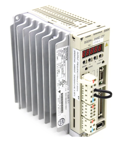
 -
 Omron 3G3HV-A4022-CE Inverter


