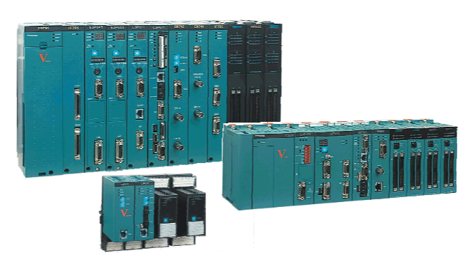
GE IS200EGPAG1A Gate Pulse Amplifier Board
GE IS200EGPAG1A Gate Pulse Amplifier Board
Part Number IS200EGPAG1A Manufacturer General Electric Country of Manufacture As Per GE Manufacturing Policy Series EX 2100e Function Module Availability In StockIS200EGPAG1A is an OBS Gate Pulse Amplifier Card manufactured by General Electric as part of the Mark VI series used in gas turbine control systems. Each of the Speedtronic systems has improved upon the preceding iteration. As a result, the MKI's modest (by today's standards) circuit boards have been replaced by the multi-frame Mark VI, which includes triple redundant backups and Ethernet functionality.
The Mark VI uses a Windows-based PC HMI, or operator interface, that provides one-stop access to critical system data, including time tags for alerts and events. The Exciter Gate Pulse Amplifier Card is an Exciter Gate Pulse Amplifier Card. The Card is intended to interface with the power bridge's control. It also accepts gate orders from the ESEL board (up to six) and utilizes them to regulate SCRS gate firing on the bridge. A line of LEDs runs along the front board edge of the components. These are used to show output firing, bridge temperature, bridge currents, alarm or fault conditions, and cooling fan rotation, among other things. There are thirteen plugs on the board.
Six two-position plugs run along the left edge, one two-position plug runs along the upper right corner and another runs along the right edge, one six-position plug runs along the front edge, and three four-position plugs run along the front edge, and a single twelve-position plug runs along the front edge.
Functional Description
IS200EGPAG1A is a Gate Pulse Amplifier Board developed by GE. It is a part of EX2100 control system. The Gate Pulse Amplifier Board (EGPA) plays a critical role in the EX2100 Excitation Control system, facilitating precise control and monitoring of the power bridge. It�receives gate commands from the ESEL (Excitation Selector) and translates them into precise control signals to manage the firing of up to six SCRs (Silicon Controlled Rectifiers) on the Power Bridge. This ensures accurate regulation of power flow within the system.
Features
Current Conduction Feedback: Acting as an interface for current conduction feedback, the EGPA monitors and provides feedback on the current flow within the system. This feedback mechanism enables real-time adjustments and ensures optimal performance and stability.
Bridge Airflow and Temperature Monitoring: Equipped with sensors to monitor bridge airflow and temperature. This monitoring capability allows for proactive management of thermal conditions within the system, helping to prevent overheating and ensure safe and reliable operation.
Power Supply Management: A nominal 125 V dc power source from the EPDM (Excitation Power Distribution Module) supplies. An onboard dc/dc converter efficiently converts this power, providing the necessary voltage for SCR gating across the full range of input supply voltage. This ensures consistent and reliable operation under varying conditions.
Visual Status Indicators: LEDs provide a visual indication of various system parameters and statuses. These indicators include the status of the EGPA power supply, input gate commands from ESEL, EGPA outputs to the SCRs, currents into the bridge, line filter status, cooling fan rotation, bridge temperature, as well as alarms or fault conditions. This visual feedback allows operators to quickly assess the status of the system and respond accordingly.
Conduction Current Sensing
Conduction currents across all three phases of the bridge input are accurately sensed and fed back to the control system.
Acts as an intermediary between Hall Effect sensors on the EXCS (Excitation Control System) boards and the control system.
Hall Effect sensors detect current flow through each leg of the three-phase bridge input, with signals transmitted to the EGPA via connectors J9-J10.
The EGPA conditions these signals before relaying the bridge status to the controller, ensuring precise monitoring and control.
Bridge Temperature Sensing
Bridge temperature is monitored using an RTD (Resistance Temperature Detector) sensor input or temperature switch input.
For new exciters, only the RTD input is utilized, with jumpers configured to disable the temperature switch inputs.
In retrofit scenarios, where an EX2100 control system is added to existing bridges, temperature switch inputs are used alongside the RTD input to interface with existing temperature switches mounted on the bridge.
Connectors J13 on the EGPA facilitate the connection of both RTD and temperature switch inputs, ensuring comprehensive temperature monitoring and control.
Airflow Sensor (Fan Rotation) Detection
Airflow sensors, specifically fan rotation, play a crucial role in detecting loss of fan cooling within the bridge.
Up to four fans can be connected to the EGPA via connector J12.
The EGPA accepts either pulsed or dry-contact, normally open sensor inputs from the fans, with the mode of signal detection configurable through berg jumpers JP2-JP4.
This flexibility allows for versatile fan monitoring and ensures timely detection of cooling system failures, preventing potential overheating and damage.
Line Filter Fuse Failure Sensing
Line filter fuse failure is detected at connector J14 on the EGPA.
This sensor input accommodates a single, normally closed, dry-contact input, providing a reliable means of monitoring the integrity of line filter fuses.
Early detection of fuse failures helps prevent system malfunctions and ensures continuous operation of the excitation control system.

- User name Member Level Quantity Specification Purchase Date
- Satisfaction :
-


