ABB NTDO01 Digital Output Termination Unit
Basic Information
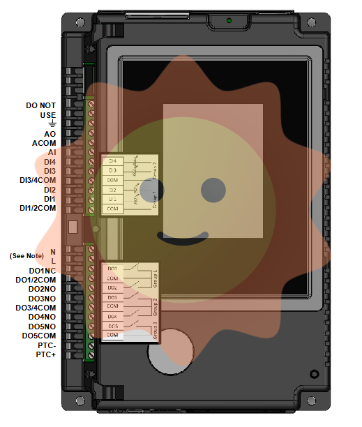
Model and name: ABB NTDO01 Digital Output Termination Unit, ‘NTDO01’ is the model identification of this product, which is a digital output terminal unit used to output digital signals in industrial automation systems or other control systems for the control of External devices.
Series: It belongs to the ABB industrial automation control equipment series, which usually includes a variety of input/output terminal units, controllers, communication modules, etc., which work together to form a complete automation control system.
Application Scenario Related: Widely used in industrial automation production lines (such as automobile manufacturing, machining, electronic assembly, etc.), process control systems (such as chemical, pharmaceutical, electric power and other industries), intelligent building automation systems (such as lighting systems, lift systems, HVAC systems) and many other fields, mainly used to control a variety of devices that require digital signal drive, such as motors, valves, indicator lights, etc.
Functional features
Digital output function
Multi-Channel Output: Usually has multiple digital output channels, the number of channels may vary depending on the specific configuration of the product, generally about 8 - 16 channels. These channels can be controlled independently, making it possible to control multiple external devices at the same time. For example, in an automation shop, one NTDO01 unit can be used to start/stop 8 different devices, such as 8 small motors or 8 valves.
Output signal type: The output digital signals are standard digital level signals, typically high (e.g. 5V or 24V DC) and low (0V), which are compatible with the majority of industrial equipment with digital interfaces. Such standard signals can be used directly to drive intermediate control elements such as relays, transistors, etc., and thus control higher power devices. For example, an output high level signal can cause a relay to engage, thus controlling the main circuit of an AC motor.
Output drive capability: Each channel has a certain output drive capability that can provide enough current to drive external devices. For example, each channel may be able to provide a current of up to several hundred milliamps (e.g. 200mA - 500mA), depending on the product design. This makes it possible to drive some low power loads directly, such as small indicator lights, solid state relays, etc., or to drive high power devices via intermediate relays.
Signal processing and control functions
Logic control realisation: Simple logic control functions can be realised. By cooperating with the controller (e.g. PLC) in the system, each output channel is controlled according to the pre-written control logic (e.g. ladder logic). For example, when a certain condition is met (e.g. the temperature sensor detects a temperature higher than the set value), the corresponding output channel is controlled according to the logic to output a high level, thus starting the cooling equipment.
Signal Synchronisation and Timing Control (possible): Some products may have signal synchronisation functions, which can synchronise the signals of multiple output channels in time, which is very useful for equipment that requires precise synchronised movements (e.g. multi-axis motion control). In addition, they may also support timing control functions, which means that the signal output time of each output channel can be set for applications such as starting/stopping equipment at regular intervals. For example, in an automated irrigation system, the output channels are timed to open and close irrigation valves at regular intervals.
Diagnostic and Monitoring Functions
Output status monitoring: enables real-time monitoring of the status of each digital output channel, including whether the current output is high or low. By monitoring the output status, it is easy to check whether the control logic is executed correctly during the debugging phase of the system, as well as to detect channel faults in time during the operation phase. For example, in a complex automated production line, if a piece of equipment does not start up as expected, by monitoring the output status of the NTDO01 unit, it is possible to quickly determine whether there is a problem with the control logic or a fault in the output channel itself.
Fault Alarm Function: A fault alarm signal can be sent when an output channel fault (e.g., short-circuit, open-circuit, etc.) is detected or when an abnormal condition such as equipment overload is detected. The alarm signal can be sent in various ways, such as lighting up the local fault indicator, sending the fault information to the upper computer system (e.g. SCADA system) or other monitoring equipment through the communication interface. In this way, maintenance personnel can receive timely notification of faults and take appropriate maintenance measures.

- User name Member Level Quantity Specification Purchase Date
- Satisfaction :
-


