
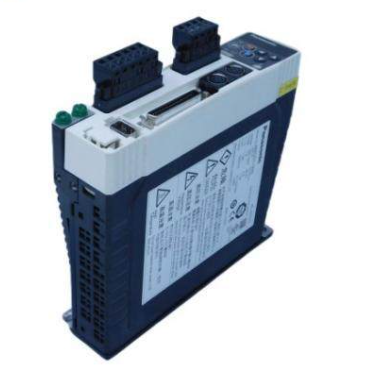
Siemens 7XV5653-0BA00 dual channel binary signal transmitter
Application scenarios
(1) Application examples
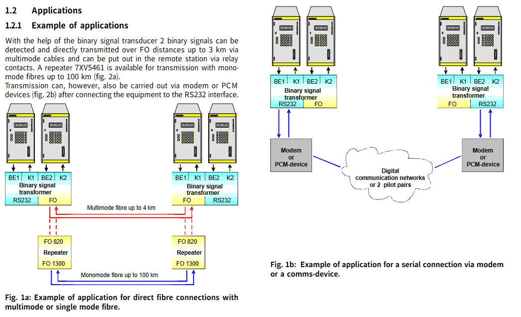
With the help of this binary signal transmitter, two binary signals can be detected and transmitted directly to a distance of 3km through multimode cables and optical fibers, and output through relay contacts at remote stations; If single-mode fiber is used for transmission up to 100km away, it can be paired with repeater 7XV5461.
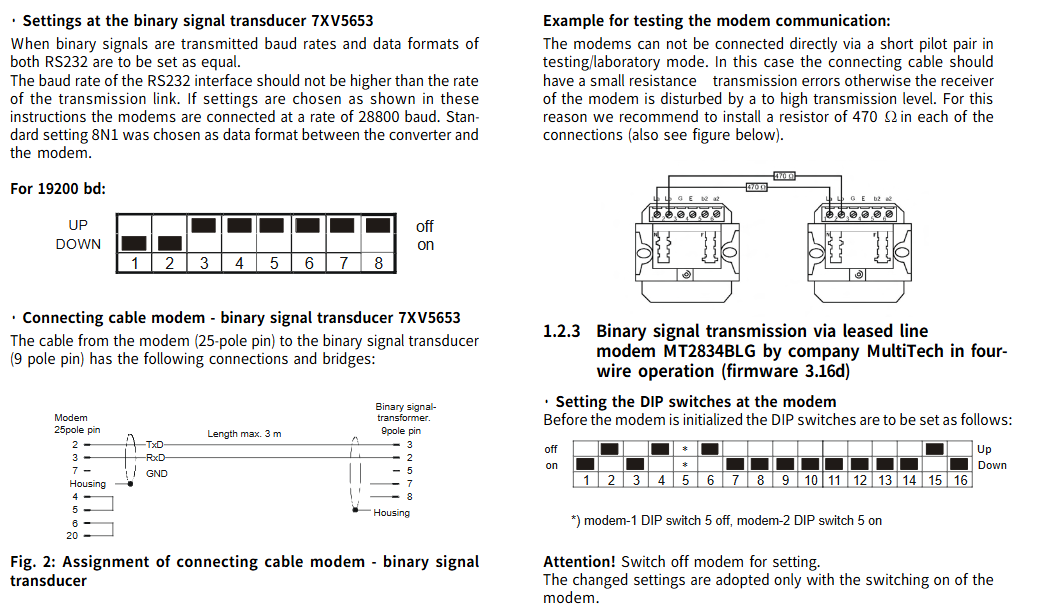
After connecting the device to the RS232 interface, it can also be transmitted through a modem or PCM device.
(2) Binary signal transmission through leased lines
1. Dual line operation using LOGEM928 and LGH28.8D modems (firmware 4.13)
DIP switch settings for modems: Before setting, the modem needs to be turned off. After setting is complete, the modem needs to be turned on for the new settings to take effect.
Modem initialization: Before debugging, the modem needs to be initialized, preferably with the help of a terminal program (such as Hyperterminal); Use a zero modem cable to connect the PC and modem running the terminal program, reset the modem before initialization (press the switch when connecting the auxiliary power supply until the LED "A/O" flashes); Enter a specific text string in the super terminal and send it. The modem will reply with "OK", and then you can disconnect the modem from the PC interface and connect its serial interface to the converter's serial interface.
The string corresponding to 19200 baud rate:
Modem A:AT &V NO Q0 &D0 F40 S51=11 %C0 S20=0 &L2 E0 Q1 &W
Modem B:AT &F0 N0 Q0 &D0 F40 S51=11 %C0 S20=0 &L3 E0 Q1 &W
Command Explanation:
|Command | Meaning|
|&F0 | Load factory settings|
|N0 | Normal mode (no data compression, no error correction)|
|Q0 | No traffic control|
|&D0 | Ignore control cable S1/108|
|F40 | Transmission mode V.34|
|S51=11 | Fixed baud rate of terminal device (RS232 interface)|
|%C0 | No data compression|
|S20=0 | Ignore symbols in the command phase|
|&L2 | Calling modem|
|&L3 | Called modem|
|E0 | No echo display|
|Q1 | Close result code|
|&W | Save the settings to the EEPROM of the modem|
Connectors and cables for dual line leased line operation: Use the accompanying cable labeled "leased line" to connect the RJ-11 connector to the socket labeled "LEASED", and connect the other end of the cable to the TAE-N encoded telephone outlet box in a specific manner (TAE-N 1 # 1 to TAE-N 2 # 1, TAE-N 1 # 2 to TAE-N 2 # 2).
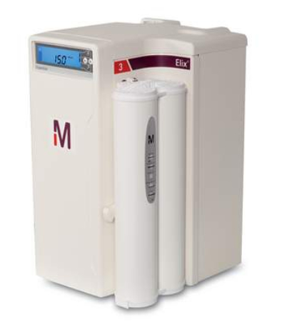
Setting of binary signal transmitter 7XV5653: When transmitting binary signals, the baud rate and data format of the two RS232 should be set to be the same; The baud rate of the RS232 interface should not be higher than the speed of the transmission link. When setting according to the instructions, the modem should be connected at a 28800 baud rate, and the data format between the converter and the modem should be set to 8N1 as the standard. The 19200 baud rate corresponds to specific DIP switch settings (DOWN/UP, off/on status).
The connection cable for modem binary signal transmitter 7XV5653: The cable from the modem (25 pin) to the binary signal transmitter (9-pin) has specific connection and bridging methods, with a maximum length of 3m.
Example of modem communication test: In test/laboratory mode, the modem cannot be directly connected through a short guide wire, otherwise excessive transmission levels will interfere with the modem's receiver. It is recommended to install a 470 Ω resistor in each connection.
2. Four wire operation using MultiTech's MT2834BLG modem (firmware 3.16d)
DIP switch settings for modem: Before setting, the modem needs to be turned off. After setting is complete, the modem needs to be turned on for the new settings to take effect. DIP switch 5 for modem 1 is set to off, DIP switch 5 for modem 2 is set to on, and other switches have specific off/on states (up/down direction).
Modem initialization: Before debugging, the modem needs to be initialized, preferably with the help of a terminal program (such as Hyperterminal); Use a zero modem cable to connect the PC and modem, input specific data (AT&FE0 # F0 $SB19200MB19200&E14&E3&W0) into the super terminal and send it, and the modem will reply with "OK".
Command Explanation:
|Command | Meaning|
|If the connection is correct, the modem replies with "OK"|
|&F | Load factory settings|
|E0 | No echo display|
|#F0 | Fixed baud rate of terminal device (RS232 interface)|
|Stable performance speed MB19200 | Fixed baud rate between modem 1 and modem 2|
|&E14 | Disable data compression|
|&E3 | Turn off traffic control|
|&W0 | Save Settings|
Connectors and cables for four line leased line operation: Use the accompanying cable labeled "leased line" to connect the RJ-11 connector to the socket labeled "LEASED", and connect the other end of the cable to the TAE-N encoded telephone outlet box in a specific way (with specific correspondence between TAE-N 1 and TAE-N 2 pins).
Technical parameters
Parameter Category Specific Parameters
Mechanical Design - Shell: Plastic EG90
-Size: See size chart
-Weight: Approximately 250g
- ABB
- General Electric
- EMERSON
- Honeywell
- HIMA
- ALSTOM
- Rolls-Royce
- MOTOROLA
- Rockwell
- Siemens
- Woodward
- YOKOGAWA
- FOXBORO
- KOLLMORGEN
- MOOG
- KB
- YAMAHA
- BENDER
- TEKTRONIX
- Westinghouse
- AMAT
- AB
- XYCOM
- Yaskawa
- B&R
- Schneider
- Kongsberg
- NI
- WATLOW
- ProSoft
- SEW
- ADVANCED
- Reliance
- TRICONEX
- METSO
- MAN
- Advantest
- STUDER
- KONGSBERG
- DANAHER MOTION
- Bently
- Galil
- EATON
- MOLEX
- DEIF
- B&W
- ZYGO
- Aerotech
- DANFOSS
- Beijer
- Moxa
- Rexroth
- Johnson
- WAGO
- TOSHIBA
- BMCM
- SMC
- HITACHI
- HIRSCHMANN
- Application field
- XP POWER
- CTI
- TRICON
- STOBER
- Thinklogical
- Horner Automation
- Meggitt
- Fanuc
- Baldor
- SHINKAWA
- Other Brands
- UniOP
- KUKA
- Iba
-
 MEYER MEYER0909 1RR1337001 Industrial Control Module
 -
 MICRO MC2-440-10TVB-1-20 Industrial Switch Data
 -
 MICROSET 104988-E03 Control Card Data
 -
 MILLIPORE WGGB12S02 Water System Module
 -
 MILLIPORE CMHT-11S02 Chemical Process Sensor
 -
 MINI MAESTRO 60X7/14 Servo Drive Technical Data
 -
 MITRA PE3257/03 High Frequency Transformer
 -
 MEYER MEYER1009 1RR1337001 Industrial Control Component
 -
 MICRO MPB1-TP Industrial Interface Terminal Module
 -
 Mitsubishi GU-D04 GOT Serial Communication Board
 -
 Mitsubishi R28TB Robot Teaching Pendant
 -
 Mitsubishi A1S68DAV 8-Channel Analog Output Module
 -
 Mitsubishi A1S65B-S1 Expansion Base Unit
 -
 Mitsubishi A1SJ51T64 I/O Link Master Module
 -
 Mitsubishi HC-KFS23K-S49 AC Servo Motor
 -
 Mitsubishi ST1X4-DE1 4-Channel Digital Input Module
 -
 Mitsubishi QM100HY-H IGBT Power Module
 -
 Mitsubishi QM100HY-H IGBT Power Module
 -
 Mitsubishi QM100DY-H IGBT Power Module
 -
 Mitsubishi BN624A96IG52A MELSECNET/H Fiber Module
 -
 MITSUBISHI BN624A960H03B Control Module
 -
 MIYACHI MA-201C Welding Control Unit
 -
 MKS 223BD-00001AAB Pressure Transducer Data
 -
 Modicon AS-BADU-204 Analog Input Module Data
 -
 Modicon AS-S908-120 Remote I/O Processor
 -
 Modicon AS-J890-002 Remote I/O Interface
 -
 Modicon NW-BM85D002 Modbus Plus Bridge Manual
 -
 Modicon AS-B875-002 24VDC Input Module Data
 -
 MKS T3BIB-29916 Control Interface Board
 -
 MKS 683B-23795 Capacitance Manometer Pressure Sensor
 -
 Molex 85003-0567 DIN 41612 Connector
 -
 MOORE 750E1B2GNNNF Temperature Transmitter
 -
 MOORE 16147-51-2 ACM Transition Board
 -
 MOORE 16147-51-02 Signal Isolator
 -
 MOORE 16407-1-1 Industrial Power Module
 -
 MOORE 42-30 Smart Electro-Pneumatic Positioner
 -
 MOORE 16310-71-1 Industrial Control Module
 -
 MOTOMAN HW9381022 Welding Robot Arm
 -
 MOX MX603-2007-01 Industrial Control Module
 -
 MOXA EDS-408A-MM-SC Industrial Ethernet Switch
 -
 M-SYSTEM MD2202-D32-X-P Digital Input Module
 -
 MTL 8811-IO-DC Digital I/O Module
 -
 MTL 8604-FT-FU Field Terminal Specification
 -
 MTL 8104-AO-IP Analog Output Module
 -
 MTL 8103-AI-TX Analog Input Specifications
 -
 MTL 8505-BI-MB Bus Interface
 -
 MTL 8711-CA-NS Carrier Module Specification
 -
 MTL MTL5514D Intrinsically Safe Interface Module
 -
 MTL MTL4544AS Isolating Interface Module
 -
 MTL 8715-CA-BI HART Transparent Isolator
 -
 MTL831B Analog Multiplexer Transmitter
 -
 MTL 8502-BI-DP Profibus DP Interface Module
 -
 MTL838B-MBF Modbus Analog Multiplexer Receiver
 -
 MTL5053 Fieldbus Intrinsic Safety Barrier
 -
 MTL 8939-HN Fiber Optic Extender IOTA
 -
 MTL 8937-HN Dual-Channel Zener Barrier
 -
 MTL 5541 Repeater Power Supply Barrier
 -
 MTL 4073 Passive Intrinsic Safety Barrier
 -
 MTL5541 Galvanic Isolated Barrier
 -
 MTL 2213 Isolated Intrinsic Safety Barrier
 -
 MTS TBF120/12TS Servo Amplifier
 -
 MTS TBF120/7R Resolver Servo Amplifier
 -
 MULLER COAX MK32NC Coaxial Connector Module
 -
 MURATA DCC2223A 3EST125-977 Power Filter Module
 -
 MURR 857781 Industrial Interface Module
 -
 MYKROLIS FC-280SAV Gas Flow Control Module
 -
 Nabtesco BTC-304 Brake Controller
 -
 NACHI UM356B Industrial Module Analysis
 -
 NACHI MFMA452D5V3 Servo Motor Specification
 -
 NACHI BUY222 Robotic Control Component
 -
 NAI 64SD1-08KRF1-13 Synchro-to-Digital Data
 -
 NAICH AUX111 Auxiliary Contact Specification
 -
 NAIS ANR5131 Micro Laser Sensor Controller
 -
 NATIONALA MM-4M-R Industrial Control Module
 -
 NEC FC-9821X MODEL2 Factory Computer
 -
 NEC FC-9801F Legacy Industrial Computer
 -
 NEC FC-9821X MODEL1 Industrial Computer
 -
 NEC FC-9821KE Industrial Panel PC
 -
 NEC RSA-983/D Embedded Industrial Computer
 -
 NEC G8NXAA5G Industrial Controller
 -
 NEC 136-551735-D-04 Genius Bus Interface
 -
 NEC SC-UPCIN-3 Industrial Control Module
 -
 NEC PC-9821XB10 Industrial Control Computer System
 -
 NEC 136-553623-A-01 Industrial Network Communication Module
 -
 NEC 136-551973-A-01 Control Processing Board
 -
 NEC 136-551733-B-02 Industrial Control Interface Module
 -
 NEUGART PLE120/115 Gearbox
 -
 NEUGART PLE120 Planetary Gearbox
 -
 NEXUS CONTROLS 369B1843G5009 Technical Data
 -
 NI NI-9694 Digital I/O Breakout
 -
 NI SBRIO-9627 Embedded Single-Board
 -
 NI SCXI-1102C Amplifier Module
 -
 NI sbRIO-9627 783817-01 Embedded Controller
 -
 NI GPIB-140A 186135G-01 GPIB Controller
 -
 NI GPIB-140A 186135F-31 GPIB Interface Card
 -
 NI GPIB-140A 186135H-01L Fiber Optic Extender
 -
 NI 192061B-02 Shielded DAQ Cable
 -
 NI SCXI-1346 Multi-Chassis Cable Adapter
 -
 NI SCXI-1600 USB Data Acquisition Module
 -
 NIBCO WD2000 Ductile Iron Butterfly Valve
 -
 NIKUNI 25KLD07Z-M Magnetic Drive Pump
 -
 NMB MAT 2410ML 05W B50 Industrial Cooling Fan High Reliability
 -
 NMS CG6565 64 2L 8TE Communication Gateway High Capacity Network Module
 -
 NMS CG6060 32 4TE1 Communication Gateway for Network Systems
 -
 NOVELLUS 02-113640-00 Industrial Control Module System Component
 -
 NOVOTRON ND32-5610VS-001-000-00 Drive
 -
 NYQUIST IOB-80 I/O Interface Board
 -
 OBERG INDUSTRIES F-DMDM-PM-110E Specifications
 -
 OCM 44A737830-001R04 Module
 -
 OEMAX NX-BASE08 8-Slot Base Plate Manual
 -
 OEMAX NX-BASE05 5-Slot Base Plate
 -
 OEMAX NX-CPU750B Basic PLC CPU
 -
 OEMAX NX-CPU750C High-Performance PLC CPU
 -
 OEMAX NX-Y16R 16-Point Relay Output Module
 -
 OEMAX NX-RTD8 8-Channel RTD Input Module
 -
 OEMAX NX-SLAVE Remote I/O Slave Module
 -
 OEMAX NX-SCU Serial Communication Unit
 -
 OEMAX NX-POSI2 2-Axis Positioning Module
 -
 OEMAX NX-DUMMY Dummy I/O Module
 -
 OEMAX NX-CPU700P PLC Controller
 -
 OEMAX NX-BASE10 PLC Backplane
 -
 OEMAX NX-AO4C 4-Channel Analog Output Module
 -
 OEMAX NX-AI8C 8-Channel Analog Input Module
 -
 OMACO GF0-57CQD-002 Industrial Control Module Precision Automation
 -
 OPTIMATE OP-620 Industrial Automation Control Module
 -
 OPTIMATE OM1510 Industrial Control Module Performance Solution
 -
 OPTO 22 SNAP-IDC5D Digital Input Module for Automation
 -
 OPTO 22 SNAP-AITM-2 Thermocouple Module


