Watlow MLS300 Series Controller
Core functions:
Ramp: Rise from the current SP to the target SP within a set time (e.g. 10 ℃/min to 200 ℃);
Soak: Maintain the target SP setting time (such as holding at 200 ℃ for 60 minutes);
Trigger and Event: Each segment can be configured with 2 digital trigger inputs (such as external signal activation) and 4 event outputs (such as initiating agitation);
Configuration steps:
Enter the SETUP RAMP/SOAK PROFILE menu, select Profile (A-Q), and set the "Time Reference" (HH: MM/MM: SS);
Edit Segment: Set "Segment Time", "Target SP", "TOLERANCE" (if ± 2 ℃, pause timing if exceeded);
Assign Profile to the target circuit, press the RAM/SOAK key to start, and the display screen will show the remaining time and current segment number in real time.
Troubleshooting and Maintenance
1. Common fault handling
Possible causes and solutions for the fault phenomenon
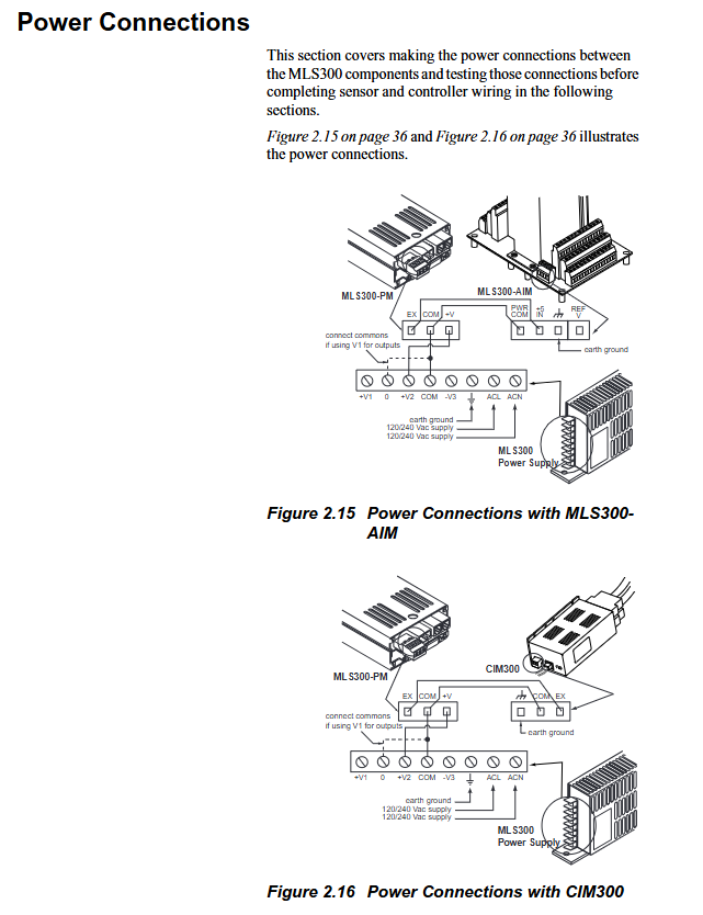
The display screen is not properly connected to the power supply, and the processor module is faulty. Check the TB1 terminal voltage (12-24V DC); Replace the processor module for testing
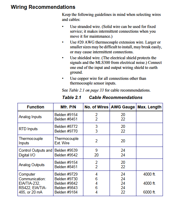
Abnormal sensor readings (high/low), incorrect sensor wiring, incorrect input type configuration, interference confirmation of thermoelectric dipole/RTD wiring; Check the "Input Type" in the Setup menu; Check the grounding of cable shielding
No response output enabled, SSR fault, loose TB50 wiring entering SETUP LOOP OUTPUTS confirmation output enabled; Measure the voltage at the SSR control terminal (conducting at 5V DC); Re tighten the terminal screws
Communication failure address/baud rate mismatch, cable failure, EIA/TIA-485 terminal resistance not connected, check the communication parameters between the controller and the upper computer; Use a multimeter to test the continuity of communication cables; Connect a 200 Ω resistor at the beginning and end of the bus
Alarm for "FS (sensor malfunction)" thermocouple open/short circuit, RTD disconnection, input module malfunction check sensor cable continuity; Replace the sensor for testing; Replace the AIM/CIM module for testing
2. Regular maintenance
Requirements for maintenance cycle operation content
Check the display screen daily for any errors and ensure that the alarm light is functioning properly; Do not wipe the display screen with alcohol when cleaning the panel and sensor; The sensor probe is free of oil stains/damage
Check the wiring terminals weekly for any looseness; Test the emergency stop and alarm function terminals and tighten the screw torque to 0.5-0.6Nm; confirm the ALARM ACK is valid after triggering the alarm
Monthly calibration of critical circuits (using standard signal sources to simulate sensor inputs); The calibration error of the cooling holes in the cleaning AIM/CIM module should be ≤ 0.1% of the full range; Compressed air blows away dust from the heat dissipation holes (pressure ≤ 0.3MPa)
Replace the processor module battery (CR2032, after power failure to avoid configuration loss) annually; Check that the battery replacement time for the shielding layer of the communication cable is ≤ 5 minutes; The shielding layer is undamaged and well grounded
Order
Ordering code rules (core position)
Code bit meaning optional values
Input module 16=AIM316 (16 channels), 32=AIM332 (32 channels) C1=CIM316、C2=CIM332 -
Firmware Type 1=Standard, 2=Extruder Specific, 3=Enhanced Features, 4=Ramp/Soak, C=Custom-
Terminal board 0=none, 1=18 pin terminal block, 2=50 pin terminal block (including 3-foot SCSI cable)-
Communication jumper 0=EIA/TIA-232, 1=EIA/TIA-485, 2=EIA/TIA-485 terminal matching-
- ABB
- General Electric
- EMERSON
- Honeywell
- HIMA
- ALSTOM
- Rolls-Royce
- MOTOROLA
- Rockwell
- Siemens
- Woodward
- YOKOGAWA
- FOXBORO
- KOLLMORGEN
- MOOG
- KB
- YAMAHA
- BENDER
- TEKTRONIX
- Westinghouse
- AMAT
- AB
- XYCOM
- Yaskawa
- B&R
- Schneider
- Kongsberg
- NI
- WATLOW
- ProSoft
- SEW
- ADVANCED
- Reliance
- TRICONEX
- METSO
- MAN
- Advantest
- STUDER
- KONGSBERG
- DANAHER MOTION
- Bently
- Galil
- EATON
- MOLEX
- Triconex
- DEIF
- B&W
- ZYGO
- Aerotech
- DANFOSS
- Beijer
- Moxa
- Rexroth
- Johnson
- WAGO
- TOSHIBA
- BMCM
- SMC
- HITACHI
- HIRSCHMANN
- Application field
- XP POWER
- CTI
- TRICON
- STOBER
- Thinklogical
- Horner Automation
- Meggitt
- Fanuc


