Watlow MLS300 Series Controller
Temperature coefficient: 40ppm/℃, ensuring measurement stability in a wide temperature environment.
2. Output and communication parameters
Parameter category specification value precautions
Digital output with 34 open collector outputs, each with a maximum sink current of 60mA (5V DC). The onboard power supply provides a total current of 350mA for controlling SSR, alarm indicator lights, etc. It can be configured as a control output or alarm output
Analog output without onboard analog output, needs to be expanded through DAC/SDAC module:
-DAC: 2-channel 4-20mA/0-5V/0-10V, accuracy ± 0.75%
-SDAC: 1 high-precision output with an accuracy of ± 0.05%. Full scale SDAC supports process variable retransmission and is suitable for scenarios that require high-precision analog signals (such as PLC analog inputs)
Serial communication interface: EIA/TIA-232 (single device, maximum 50m), EIA/TIA-485 (multi device, maximum 4000ft);
Baud rate: 2400/9600/19200bps;
Protocol: Modbus RTU, Anafaze protocol, Allen Bradley PLC/2 compatible protocol EIA/TIA-485 supports networking of 32 devices and requires 200 Ω terminal resistors to be configured at both ends of the bus
Power requirements: Processor module: 12-24V DC ± 15%, maximum 1A;
AIM/CIM module: 5V DC (provided by the processor module). It is recommended to use an isolated power supply to avoid sharing the circuit with high-power devices and reduce interference
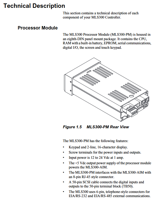
Installation and wiring specifications
1. Pre installation requirements
Environmental conditions: working temperature 0-50 ℃, storage temperature -20-60 ℃, relative humidity 10% -95% (no condensation); Keep away from strong electromagnetic interference sources (such as frequency converters and high-voltage cables) and avoid vibration (amplitude ≤ 0.5mm, frequency ≤ 50Hz).
Qualification requirements: Installation personnel must have industrial electrical installation qualifications, and high-voltage wiring (such as power module input) must be operated by certified electricians; Prepare torque wrenches (0.5-0.6Nm), shielded cables, crimping tools, etc.
Space requirements: A 1.96 × 3.78-inch (50 × 96mm) opening should be reserved for the installation of the processor module panel, and a wiring space of ≥ 7.4 inches (188mm) should be reserved on the back; The AIM module requires a reserved installation space of 6.5 x 5 x 5.75 inches (165 x 127 x 146mm).
2. Installation steps of core components
(1) Processor module (MLS300-PM)
Cut 1.8 × 3.63 inch (46 × 92mm) openings on the panel, remove module brackets and baffles;
Insert the module into the opening, fit the installation ring on the back, fix the upper and lower brackets, and tighten the screws (torque 0.5Nm);
Connect the AIM/CIM communication cable (RJ45 interface, labeled "To AIM"), TB50 50 50 pin SCSI cable, and power supply (TB1 terminal:+V to 12-24V DC, COM to negative pole).
(2) Input module (AIM/CIM)
AIM module:
Fix the AIM-TB terminal board with 4 # 6 screws to ensure grounding (grounding resistance ≤ 4 Ω);
Connect sensor cables: thermocouple "+" is connected to A+, "-" is connected to A -; RTD 3-wire system requires the "common end" to be connected to A COM, and the "signal end" to be connected to A+/A -;
Connect AIM to the processor module via RJ45 cable and test AIM power supply (TB3 terminal:+5 IN to PWR COM voltage 4.75-5.25V DC).
CIM module:
Support DIN rail or direct installation, connect sensors through D-Sub 50 connectors (J1 for 16 channels, J2 for 32 channel expansion);
Communication cable (RJ45) connected to CIM J3 interface, power supply (TB2 terminal: EX connected to processor EX, COM connected to processor COM).
(3) Terminal board (TB50)
Choose DIN rail or bracket installation, connect 50 pin SCSI cable to the processor module;
Wiring specifications:
Digital output (terminals 9-42): When controlling SSR, connect+5V to the positive pole of SSR and connect the output terminal to the negative pole of SSR;
Digital input (terminals 43-50): One end of the external switch is connected to the input terminal, and the other end is connected to CTRL COM (terminal 3/4);
Power terminal (1-2):+5V is the output (for SSR, etc.), CTRL COM is the common terminal, and grounding is prohibited.
3. Wiring and anti-interference requirements
Recommended specifications for cable types and wiring requirements
Sensor cable thermocouple: 20AWG thermocouple extension wire; RTD: 22AWG shielded twisted pair cable; Linear signal: 22AWG shielded twisted pair cable should be kept away from high-voltage cables (≥ 10cm), and the shielding layer should be grounded at one end (processor end); RTD cable length ≤ 100m
Control the output cable with 24AWG multi-core shielded wire and separate it from the input cable to avoid parallel laying; SSR control line length ≤ 50m
Communication cable EIA/TIA-232: Belden 9729 (6-core shielded wire, ≤ 50m); EIA/TIA-485: Shielded 9843 (4-core shielded twisted pair, ≤ 1200m) with both ends of the shielding layer grounded; The EIA/TIA-485 bus requires a 200 Ω terminal resistor to be configured at both ends
Basic Operations and Configuration
1. Startup and initialization
- ABB
- General Electric
- EMERSON
- Honeywell
- HIMA
- ALSTOM
- Rolls-Royce
- MOTOROLA
- Rockwell
- Siemens
- Woodward
- YOKOGAWA
- FOXBORO
- KOLLMORGEN
- MOOG
- KB
- YAMAHA
- BENDER
- TEKTRONIX
- Westinghouse
- AMAT
- AB
- XYCOM
- Yaskawa
- B&R
- Schneider
- Kongsberg
- NI
- WATLOW
- ProSoft
- SEW
- ADVANCED
- Reliance
- TRICONEX
- METSO
- MAN
- Advantest
- STUDER
- KONGSBERG
- DANAHER MOTION
- Bently
- Galil
- EATON
- MOLEX
- Triconex
- DEIF
- B&W
- ZYGO
- Aerotech
- DANFOSS
- Beijer
- Moxa
- Rexroth
- Johnson
- WAGO
- TOSHIBA
- BMCM
- SMC
- HITACHI
- HIRSCHMANN
- Application field
- XP POWER
- CTI
- TRICON
- STOBER
- Thinklogical
- Horner Automation
- Meggitt
- Fanuc


