
Yokogawa Motor YS1700 Programmable Indicator Controller
Standard models are smaller and lighter than earlier series,requiring less space for installation, and are compliant with international safety standards including the CE Mark and FM,CSA nonincendive (optional) approvals. For easy replacement of earlier controllers, models requiring the same panel cutout dimensions and depth as those of earlier models are also offered.
Yokogawa Motor YS1700 Programmable Indicator Controller
FEATURES
Product Model Classification and I/O Configuration
YS1700 is divided into multiple models based on functionality and compatibility, with the core difference reflected in the number of I/O interfaces and compatibility with older devices. The specific parameters are shown in the table below:
Model Type Model Identification Analog Input (AI) Analog Output (AO) Digital Input/Output (DI/DO) Core Features
Basic YS1700-x0x 5 (1-5V DC) 2-channel 1-5V DC (1 channel can be changed to 4-20mA) 6 (DI/DO shared) Basic function, no expansion I/O, protection level IP54
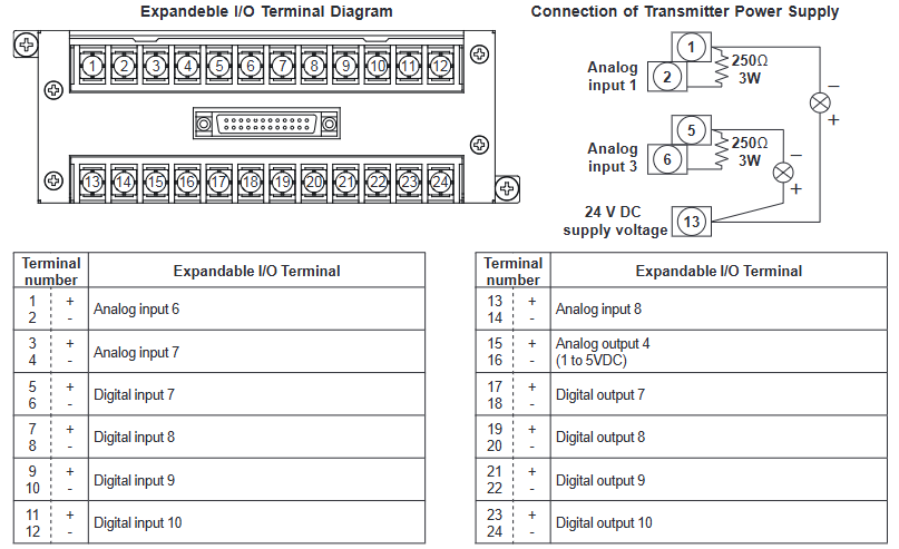
Scalable I/O Basic YS1700-x1x 8 (including 3 extensions) 3 1-5V DC+1 4-20mA 14 (including 4 extensions) Supports I/O extensions, suitable for complex signal acquisition scenarios
YS100 compatible YS1700-x2x (/Ax) 5 (4 channels available) 2 channels 1-5V DC (1 channel can be changed to 4-20mA) 6 compatible YS100 series, signal terminal layout close to the old model
YS80 internal unit compatible YS1700-x3x 5 2-channel 1-5V DC (1 channel can be changed to 4-20mA) 6 compatible with old devices such as YS80, EBS, I, EK, HOMAC, etc
YS80 (YS100 terminal) compatible YS1700-x4x (/Ax) 5 (4 channels available) 2 channels 1-5V DC (1 channel can be changed to 4-20mA) 6 sizes compatible with YS80, terminal layout matching YS100
100 wire (YS100 terminal) compatible YS1700-x5x (/Ax) 5 (4 channels available) 2 channels 1-5V DC (1 channel can be changed to 4-20mA) 6 compatible with 100 wire pneumatic instrument replacement scenarios
Note: Some analog inputs can be changed to 4-20mA through parameter settings, and DI/DO terminals can be specified as input or output functions through parameters.
Core functions and technical features
1. Display and operation functions
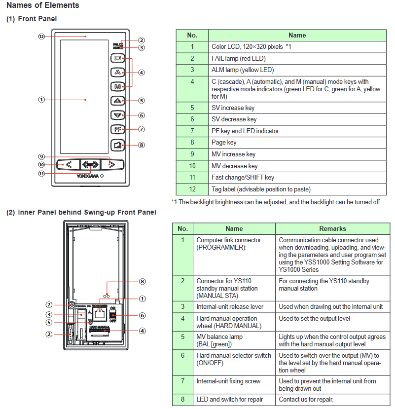
High visibility display: using a 120 × 320 pixel full dot matrix TFT color LCD, supporting backlight brightness adjustment and off, even in direct sunlight in the morning and evening, it is still clearly visible; Provide multiple display modes such as dashboard, trend chart, bar chart, alarm, event, etc., which can be quickly switched through panel buttons.
Flexible data display: The tag number can display up to 12 characters, PV (process value) and SV (set value) can display up to 7 digits (including decimal point and symbol), and MV (operation value) can display up to 6 digits; The trend chart supports three types of variables (such as PV1/SV1/MV1), with a time span of 1.5 minutes to 45 hours, and can hide/display a single curve.
Convenient manual operation: The panel is equipped with SV/MV increase and decrease buttons, supporting FAST mode (MV adjustment speed 4 seconds/full range, normal mode 40 seconds/full range); When there is a malfunction, it automatically switches to FAIL display, and the hard manual wheel can adjust the output urgently.
2. Control mode and computing power
Dual control mode:
Programmable mode: Requires YSS1000 configuration software, supports basic control (BSC1/BSC2), cascade control (CSC), selector control (SSC) modules, and can freely combine control and calculation modules.
Function selection mode: No programming required, select commonly used functions (single loop, cascade, selector control) directly, and I/O functions are allocated through parameters.
Rich control types: Supports four control types: PID, PD, sample and hold PI, and batch PID. PID parameters (proportional range 0.1-999.9%, integration time 1-9999 seconds, differentiation time 0-9999 seconds) can be flexibly set, and additional functions such as self-tuning (STC), nonlinear PID, and output limitation can be added.
High precision calculation: using IEEE754 format 4-byte floating-point operation, supporting over 100 calculation modules such as exponential, logarithmic, temperature/pressure compensation, etc., to ensure data processing accuracy.
3. Programming and debugging skills
Dual programming mode:
Text programming: Program capacity of 1000 steps (main program+subroutines, subroutines can be reused), supporting logical operations, conditional judgments, jumps, and other instructions.
Function block programming: Based on GUI interface, with a program capacity of 400 modules, supporting online monitoring and testing operation, reducing programming barriers.
Online debugging: Through YSS1000 software, program testing, I/O signal simulation (up to 50 steps of simulation program), and functional block status monitoring can be achieved for easy troubleshooting and parameter optimization.
Data storage: Provides 30 P-parameter variables, 100 K-parameter constants, and 60 temporary data registers to meet the data storage needs of complex programs.
4. Communication function
Support multi protocol communication and adapt to different industrial control systems, with specific parameters as follows:
Key parameters of communication type interface/protocol applicable scenarios
RS-485 PC Link, Modbus RTU/ASCII, YS protocol, point-to-point communication connection PLC, PC or multiple YS1700 devices can be networked up to 32 devices, with a maximum communication distance of 1200 meters
Ethernet Modbus/TCP (basic type only) connection DCS/PLC, supports remote configuration and monitoring 10BASE-T/100BASE-TX, RJ45 interface, distance of 100 meters
DCS-LCS communication Yokogawa dedicated protocol connects up to 8 devices per LCS card in Yokogawa CENTUM CS 3000 and other DCS systems, with a communication distance of 100 meters
Programmer communication RS-232C (dedicated interface) downloads/uploads programs and parameters through YSS1000 software using a dedicated USB-RS232C cable, with a distance of approximately 2.7 meters
Host control mode: Supports DDC (direct control MV) and SPC (control SV) modes, and can automatically switch to manual (MAN) or automatic (AUT) backup mode when communication is interrupted.
Wiring cost optimization: Modbus multi station output supports 32 devices sharing one communication cable, reducing wiring workload.
5. Alarm and self diagnosis
Alarm function: Supports PV high and low limit/high and high limit/low and low limit alarms, deviation alarms, and rate alarms. The alarm threshold (-6.3-106.3%) and hysteresis (0.1-20.0%) can be set; When an alarm is triggered, the ALM yellow light will light up, the tag number will be displayed in reverse, and the event message can be stored and traced back on the ALARM interface (up to 5 messages).
Self diagnosis: It can detect hardware faults such as CPU failure, A/D/D/A conversion errors, memory errors, etc. When there is a fault, the FAIL red light will light up, the analog output will maintain the current value, the DO signal will be locked, and the hard manual function will be enabled.
Hardware specifications and environmental adaptability
1. Input and output electrical parameters
Signal type specification parameter accuracy requirements
Analog input (1-5V) input resistance 1M Ω, range 0-5.5V, supports direct input (mV, thermocouple, RTD, etc.) ± 0.1% range (basic type), ± 0.2% range (extended I/O)
Analog output (4-20mA) load resistance 0-750 Ω, output range 0.8-21.0mA ± 0.2% range
Digital input with no voltage contacts (below 200 Ω/above 100k Ω), voltage contacts (low -0.5-1V/high 4.5-30V), minimum pulse width of 70-220ms (according to control cycle)
Digital output transistor contact, open circuit output in case of 30V DC/200mA (resistive load) fault
Transmitter power supply 25-25.5V DC, load below 60mA (including 30mA below direct input) short circuit protection 80 ± 10mA
2. Environmental and mechanical characteristics
Working conditions: temperature 0-50 ℃, humidity 5-90% (non condensing), altitude below 2000 meters, atmospheric pressure 86-106kPa; Anti vibration (5-14Hz amplitude 0.625mm, 14-150Hz acceleration 4.9m/s ²), anti impact (49m/s ², within 11ms).
Protection and material: Basic panel protection IP54, shell 316 stainless steel; Insulation resistance 100M Ω (500V DC), withstand voltage 1000-3000V AC (depending on model), in compliance with IEC/EN 61010 safety standards.
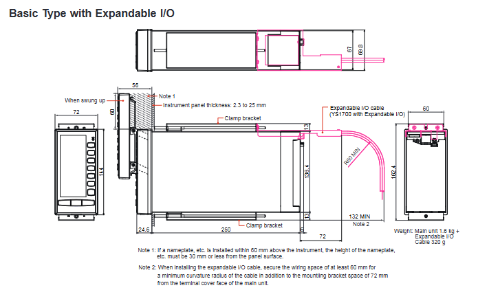
Size and Installation: The basic size is 144 × 72 × 250mm (H × W × D), with a panel opening of 137 × 68mm. It supports parallel installation, and the opening width needs to be adjusted according to the quantity when installing multiple devices (such as 2 units of 140mm and 3 units of 212mm).
Safety Compliance and Certification
General safety standards: comply with IEC/EN 61010-1/2-201/2-030, CAN/CSA-C22.2 No.61010 series standards, overvoltage category II, pollution level 2, measurement category O.
EMC standards: EN 61326 Class A, EN 55011 Class A Group 1, anti common mode noise 83dB, series mode noise 46dB (50/60Hz).
Hazardous Area Certification: Optional FM/CSA non flammable certification (Class I, Division 2, Groups A-D, Temperature Class T4), suitable for potentially explosive environments.
Environmental standards: Compliant with the EU RoHS directive (EN IEC 63000), with no harmful substances except for the A08 frequency input option.
Installation and Accessories
1. Installation requirements
Panel installation: The panel thickness is 2.3-25mm, with at least 60mm of space reserved at the top (to avoid obstruction during operation), and 100mm of ventilation space reserved above and below.
Expansion I/O installation: The expandable I/O type requires YS010 expansion terminals and YS011-03 expansion cables (3 meters), with a cable bending radius of ≥ 60mm.
Wiring specifications: The signal terminal and power terminal are both M4 screws. Shielded twisted pair cables are required for analog signals, and grounding must comply with Yokogawa grounding specifications.
2. Standard and optional accessories
Accessory type, model, purpose, and remarks
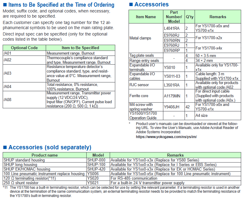
Install brackets L4041RA, E9760RJ, and other fixed controllers onto the panel to adapt to different compatible controllers of different models
Expansion I/O accessories YS010 (terminal), YS011-03 (cable) are only applicable for expandable I/O type signal expansion YS1700-x1x
Temperature compensation accessory L3501RA (RJC sensor) thermocouple input reference compensation only/A02 option applicable
YS020 (120 Ω terminal resistor) and YS021 (250 Ω shunt resistor) resistor accessories are suitable for RS-485 communication matching and signal conversion. The terminal resistors can be enabled or not by parameter selection
Replace the shell SHUP-000/SHUP-100/SHUP-420, YS006 to adapt to the installation of old equipment, such as YS80 and 100 line instruments, and select the corresponding shell according to the compatible model
- OMRON
- ABB
- General Electric
- EMERSON
- Honeywell
- HIMA
- ALSTOM
- Rolls-Royce
- MOTOROLA
- Rockwell
- Siemens
- Woodward
- YOKOGAWA
- FOXBORO
- KOLLMORGEN
- MOOG
- KB
- YAMAHA
- BENDER
- TEKTRONIX
- Westinghouse
- AMAT
- AB
- XYCOM
- Yaskawa
- B&R
- Schneider
- KONGSBERG
- NI
- WATLOW
- ProSoft
- SEW
- ADVANCED
- Reliance
- TRICONEX
- METSO
- MAN
- Advantest
- STUDER
- DANAHER MOTION
- Bently
- Galil
- EATON
- MOLEX
- DEIF
- B&W
- ZYGO
- Aerotech
- DANFOSS
- Beijer
- Moxa
- Rexroth
- Johnson
- WAGO
- TOSHIBA
- BMCM
- SMC
- HITACHI
- HIRSCHMANN
- Application field
- XP POWER
- CTI
- TRICON
- STOBER
- Thinklogical
- Horner Automation
- Meggitt
- Fanuc
- Baldor
- SHINKAWA
- Other Brands
- UniOP
- KUKA
- Iba
- Beckhoff
- ADLINK
-
 LTI SC52.0040.0012.0000.0 Compact Servo Drive
 -
LTI Tools LT4400-30 Twist Socket 1/2 inch Drive
-
 Lust LTi CDE32.008 Position Controller
 -
 LUST B-DS 125.1 LTi Drives 181-00635 Module
 -
 LTI DRIVES MS100 Montageset 0927.0017
 -
 Lust LTi Servo One SO84.032.0043.0000.2 Drive
 -
 LTI CDF 30.008.C3.6 Drive Power Supply
 -
 LTI SC52.0040.0012.0000.0 Servo Drive
 -
 LTi Drive CDF30.002 Power Supply Fuse
 -
 LTI Tools LT-4621-D Deep Well Twist Socket
 -
 MOOG LTI CDE54.044.D Pitch Master Turbine Drive
 -
 LTI TOOLS LT-1460 Wheel Torque Extension Kit
 -
 LUST LTi SO82.004.0030.0000.2 Servo Drive
 -
 LTI MOTION SA54.0075.0033.0000.0 Servo Drive
 -
 LUST LTi CDE34.006 W2.0 BR Servo Drive
 -
LUST LTi MOTION CDE34.044 W2.4 H13 Servo Drive
-
LUST LTi CDE32.008 W2.2.BR Positioning Controller
-
 LUST LTi DRiVES B-DS 125.1 Braking Resistor
 -
 LTI MOTION CDE34.006.WXX.PC1 Servo Drive
 -
 LTI MOTION SO24.007.0030.1000.0 Servo Drive
 -
Lust CDD34.005.C2.1 LTI Drive
-
LTI SC52.0040.0012.0000.0 Compact Servo Drive
-
LTI Tools LT4400-30 Twist Socket 1/2 inch Drive
-
 Lust LTi CDE32.008 Position Controller
 -
 LUST B-DS 125.1 LTi Drives 181-00635 Module
 -
LTI DRIVES MS100 Montageset 0927.0017
-
 Lust LTi Servo One SO84.032.0043.0000.2 Drive
 -
LTI CDF 30.008.C3.6 Drive Power Supply
-
LTI SC52.0040.0012.0000.0 Servo Drive
-
LTi Drive CDF30.002 Power Supply Fuse
-
LTI Tools LT-4621-D Deep Well Twist Socket
-
 LTI Tools LT-1400C Wheel Torque Extension
 -
LTI SO CM-P.0122.2015.1 Servo Drive SA000-13029N
-
LTI MOTION SC32.0075.1011.0000.0 Servo Drive
-
 LTI MOTION SC34.0200.0011.0000.0-SL Servo Drive
 -
 LTI CDE34.017 W2.4 H18 Frequency Inverter
 -
 LTI SO CM-P.0122.2015.1 Servo Drive
 -
 LTI FLPF-142-3-12-560/T4 Servomotor
 -
 MOOG LTI CDE54.044.D Pitchmaster Turbine Drive
 -
Lust LTi CDB34.003.C2.4 SH Servo Controller
-
 LTI SC52.0040.0012.0000.0 Servo Drive
 -
LTI SA52.0100.0033.0000.0 Servo Driver
-
 LUST CDE 54.044.D Pitch Master Turbine Drive
 -
 Lust LTi Servo One SO84.032.0040.0000.2 Drive
 -
 LTi LSH-074-2-60-560/T1 P S4 B14.1R Servo Motor
 -
LTI SC52.0040.0012.0000.0 Servo Drive
-
 LTI CDS44.072.LC1.1.NF Servo Driver
 -
 LTI SO CM-P.0122.2015.1 Servo Drive
 -
LTI MOTION SO24.007.0030.1000.0 Servo Drive
-
LTI MOTION SC34.0300.0011.0000.0 Servo Drive
-
 LTI DRIVES GmbH MS100 Mounting Set 0927.0017
 -
 LTI CDB34.014 W2.4 BR SH Servo Driver
 -
LTi Drives 0920.0034.14 Documentation DVD
-
 LTI MOOG CDE54.044 Pitchmaster Frequency Converter 181-01019
 -
LTI LSN-097-0960-30-560 Servo Motor
-
LUST LTI CDE32.008 W2.2.BR Positioning Controller
-
LTI Drives MS100 0927.0017 Assembly Set
-
 LTI SO82.004.0030.0000.2 Servo Drive
 -
LTI MOTION SC32.0040.1011.0000.0 Servo Drive
-
LTi Drives 0920.0034.14 Product DVD
-
LTI MOOG CDE54.044 Pitchmaster Servo Drive 181-01019
-
LUST LTI CDE34.017 W2.4 Servo Drive
-
 Lust LTi Servo One SO84.032.0040.0000.2 Drive
 -
 LUST LTI SO84.012.0011.1700.2 Servo Drive
 -
LTI LSN-097-0960-30-560 Servo Motor
-
LUST CDE 54.044.D Pitch Master Turbine Drive
-
 LTI Luster SA54.0550.0033.0000.0 Servo Drive
 -
LTI CDS44.072.LC1.1.NF Servo Driver
-
 LTI DRIVES GmbH MS100 Assembly Set 0927.0017
 -
 LTi Drives DSM4-14.2-21R83-200 Servo Motor
 -
LTI Motion SC52.0150.0012.0000.0 Servo Drive
-
LTI Motion LSP04-004-048-60-0PR1PY17E0440 Servo Motor
-
 LTI KP300-R Drive Interface Operator Display
 -
 Lust LTI SO84.020.0002.0100.2 Servo Drive
 -
 LUST LTI CDD34.008.W2.1 CDD3000 Servo Drive
 -
LTI MOTION SA54.0550.0033.0000.0 Servo Drive
-
 LTI Drives MS100 0927.0017 Mounting Kit
 -
 LTi DRiVES LSP06-015-320-30-00H1MY170 Servo Motor
 -
 LTI MC6412 C1 D3 S12 Servo Drive
 -
LUST LTi SO82.004.0030.0000.2 Servo Drive
-
LTi Drives LSP06-015-320-30-00H1MY170 Servomotor
-
LUST LTi CDE34.003 C2.0 Servo Drive
-
LUST LTi LSH-127-1-30-560 T1 Servo Motor
-
 LTI MOOG CDE54.044 Pitchmaster Servo Drive
 -
LTI Lock Technology 1237 Flip Socket Set
-
LTi LSP08-028-560-55-00H1MY1M0 Servomotor
-
Lust LTi CDE34.010.D2.4 Position Controller 10A
-
 Lust LTi CDE34.010.D2.4 Positioning Controller 10A
 -
LTi Drives FLPF-142-3-12-560/T4 Servomotor
-
 LUST LTI Motion CDD54.045 W2.1 Servo Drive
 -
LUST LTI CDD34.006.W2.2.PC1 Servo Drive
-
 LTI KP200-XL Operator Panel Keypad 4 Key
 -
 Lust LTI CDE32.008 W2.2.BR Positioning Controller
 -
LTI Servo One SO82.004.0030.0000.2 Drive Amplifier
-
LTI MOTION SC54.0550.0012.0000.0 Servo Drive
-
LTI LSN-097-0510-30-560 Servo Motor
-
LTi Drives 0920.0034.14 Product DVD
-
LTI SO82.004.0030.0000.2 Servo Drive
-
MOOG LTI CDE54.044 Pitchmaster Frequency Converter
-
LUST LTI CDE34.017 W3.0 Servo Drive
-
LUST LTi Drives CDS44.072 LC1.1 Servo Drive
-
LUST LTi DC1-3.0006.1000.0 Servo Drive
-
LTi LSMM13-100-4N-001 Servo Motor
-
LTI MOOG CDE54.044 Pitchmaster Servo Drive
-
 LUST LTi Drives NFE12.3 Line Filter
 -
LTI MOTION SC34.0100.1011.0000.0 Drive
-
LUST LTi LSH-074-2-30-560/T1 B S4 G6.1M Servomotor
-
LUST LTI CDE34.044W2.3 Servo Drive
-
LUST LTi LST-127-5-15-560/T1 S4 G12.1S Servomotor
-
Lust LTi MOTION CDE34.044 W2.4 H13 Servo Drive
-
LTI Servo One SO82.004.0030.0000.2 Drive Amplifier
-
Lust LTI CDE34.006 W2.4 V4.10-02 Servo Controller
-
LTI Drives Stromag FLP 20/0014-60 BA 1 Servomotor
-
Lust LTI CDE34.024.Wx.x.PC1 Servo Controller
-
LTI Drives FLP13-0395-30-AC2 9.5 kW Servo Motor
-
LTI CDB32.004-C2.0SH Servo Drive
-
LTi LSH-074-2-30-320/T1 1R Servo Motor
-
LTi DRiVES LSP08-028-320-30-BPH2MY17E0803 Servo Motor
-
LUST LTI SO24.007.0020.0000.1 Servo Controller
-
LTI CDE34.017.W3.0 Frequency Inverter
-
LUST LTi DRIVES LSH-097-0960-30-560/T1 Servomotor
-
LTi DRiVES LSP10-056-560-50-00H1MY 1M0 Servomotor
-
LTi DRiVES LSP08-028-320-55-00H1MY 170 Servomotor
-
 LTI MC6432 C1 D3 S12 G20 Servo Drive
 -
 Keba LTi CDE32.008 C3.0 Frequency Inverter
 -
Lust LTI CDE32.004 C2.4 V4.10-02 Servo Controller
-
LTI SO CM-P.0122.2015.1 Servo Drive
-
LUST LTi LST-127-2-30-560/T1 Servomotor


