
SIEMENS SIMOTICS 1LE8 series low-voltage high-power motor
Comparison dimension 1LE8003 (universal type) 1LE8033 (frequency conversion specific type)
SIEMENS SIMOTICS 1LE8 series low-voltage high-power motor
Product Overview and Core Parameters
1. Series positioning and differences in sub series
The SIMOTICS 1LE8 series is a low-voltage high-power motor developed by Siemens specifically for the Chinese market. Based on a global design platform, it focuses on high reliability and high power density and is divided into two sub series. The core differences are shown in the table below:
Comparison dimension 1LE8003 (universal type) 1LE8033 (frequency conversion specific type)
Core use: General scenario (mainly direct supply, optional frequency conversion) Frequency conversion specific scenario (≤ 690V), suitable for steel, lifting, etc
Insulation usage level: 130 (B) for direct supply, 155 (F) for variable frequency, and 155 (F) for variable frequency operation
Bearing configuration: Deep groove ball/angular contact ball bearings (optional insulated bearings), standard insulated bearings (anti stray current damage)
Temperature protection optional PTC/PT100/PT1000 standard dual group PTC (145 ℃ alarm/155 ℃ trip)
Variable frequency voltage upper limit ≤ 460V ≤ 690V (optional N90 special insulation, no need for variable frequency filter)
2. Core rated parameters (50Hz)
Machine base number, pole number, rated power range (kW), rated speed (rpm), efficiency (4/4 load,%), power factor (4/4 load), weight (IMB3, kg)
315 2 220~315 2978~2982 95.8 0.89~0.91 1380~1590
315 4 220~315 1490~1491 96.0 0.85 1480~1650
315 6 160~250 990~991 95.8 0.85 1370~1700
315 8 132~200 740~741 94.0~94.6 0.80 1320~1690
355 2 355~500 2982~2988 95.8 0.89 2200~2300
355 4 355~500 1490~1491 96.0 0.85~0.87 1960~2290
355 6 280~400 993~994 95.8 0.85 2150~2270
355 8 220~315 743~745 94.6 0.81 2140~2250
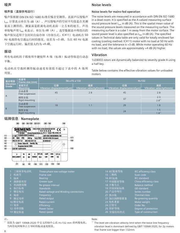
Detailed explanation of mechanical characteristics
1. Structure and installation
Machine base and appearance: The machine base material is gray cast iron, standard color RAL7030 (stone gray), supports multiple installation structures (compliant with IEC 60034-7), and the core installation types and codes are as follows:
Installation type code (14th digit of order number) Applicable scenarios
IM B3 A machine base with feet, end cover without flange
IM B35 J machine base with feet, end cover with flange
The IM V1 G machine base does not have feet, and the end cover has a flange
Junction box: standard top mounted (order number 16th digit is 4), rotatable 4 × 90 °, supports upper right (5) and upper left (6) configurations; The 315 machine base contains 2 main inlet holes (M72 × 2), and the 355 machine base contains 3 main inlet holes, all of which are sealed with screw plugs. The maximum number of auxiliary terminals is 24 (L97 auxiliary junction box is required for excess).
2. Bearings and lubrication
Bearing configuration: The standard is deep groove ball bearings (6316 C4 for 315 machine base 2-pole, 6319 C4 for 4-8 pole; 6317 C4 for 355 machine base 2-pole, 6320 C4 for 4-8 pole), and 1LE8033 comes with insulated bearings as standard; The L22 enhanced design (with cylindrical roller bearings on the drive end) is available for high arm suspension scenarios.
Lubrication parameters (horizontal installation, 40 ℃ environment):
Machine base number, pole number, lubrication cycle (h), amount of grease added (g)
315 2 3000 30
315 4 4000 40
315 6/8 6000 40
355 2 3000 30
355 4 4000 60
355 6/8 6000 60
Note: For every 10 ℃ increase in ambient temperature, the lubrication cycle is shortened by 50%.
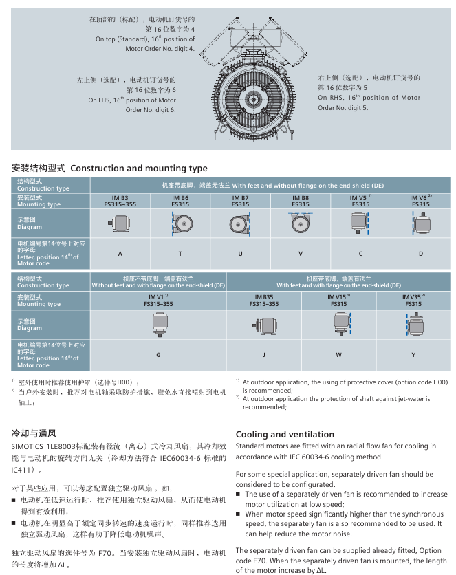
3. Cooling method
Standard configuration: IC411 self fan cooling (radial centrifugal fan, independent of rotation direction);
Optional: F70 independent drive fan (recommended for low speed/over rated speed to reduce noise), the motor length increases by Δ L after installation (315 base+180mm, 355 base+150mm), and the fan parameters are 220V Δ/380VY, 50Hz, 1100W.
Electrical characteristics and protection
1. Voltage and frequency adaptability
Voltage deviation: Supports deviation between Class A (± 5%) and Class B (± 10%) of IEC 60034-1, with a temperature increase of approximately 10K for Class A and long-term operation not recommended for Class B;
Frequency deviation: Class A ± 2%, Class B+3%/-5%;
Core voltage configuration:
1LE8003:380VΔ/660VY、400VΔ/690VY(50Hz);
1LE8033: 500V Δ (standard), 690VY (options 0-6).
2. Motor protection
Winding protection: Supports PTC, PT100, PT1000 three types of components, and the selection corresponds to the 15th digit code of the order number:
Protection type code, number of wiring terminals, core parameters
Unprotected A --
Single set PTC (trip 155 ℃) B 2 three core series connection, suitable for heavy-duty starting
Dual group PTC (alarm 145 ℃/trip 155 ℃) C 4 1LE8033 standard configuration
3 2-wire PT100 H 6 with high precision and good linearity
1 2-wire PT1000 K 2 for more accurate temperature monitoring
Bearing protection: optional Q72 (dual ended 2-wire PT100, 4 terminals), Q78 (dual ended 3-wire PT100, 6 terminals), Q79 (dual ended dual supported 3-wire PT100, 12 terminals);
Moisture protection: Options Q04 (1LE8003)/Q02 (1LE8033), 220V, 100W moisture-proof heating belt, works when stopped and closes when running to avoid winding condensation.
3. Characteristics of frequency conversion applications
1LE8003: Variable frequency voltage ≤ 460V, maximum safe speed 3600rpm (2-pole), frequency exceeding 60Hz requires special dynamic balancing;
1LE8033: Variable frequency voltage ≤ 690V, maximum safe speed 3600rpm (2-pole), peak voltage withstand value 3200Vpp (690V variable frequency), supports field weakening operation, and requires forced cooling when the load torque exceeds the limit.
Selection and Option Configuration
1. Order number rules (16 digit code)
Taking 1LE8003-3AA33-3 □□□□ as an example, the meaning of key positions is:
Explanation of the meaning of digits and example values
1-6 series identification 1LE800/1LE803
7 sub series 3=1LE8003, 3=1LE8033
8-9 aircraft seat number 3A=315, 3B=355
10 poles A=2, B=4, C=6, D=8
11-12 Voltage/Frequency 33=380V Δ/660VY 50Hz
13 iron core length 3=standard length
Installation type A=IM B3, J=IM B35
15 winding protection B=single group PTC, C=double group PTC
16 junction box position 4=top mounted, 5=upper right side, 6=upper left side
2. Core Option List
Option Number Function Description Applicable Scenarios
L22 enhanced cantilever force design (with cylindrical roller bearings at the drive end) for high radial loads (such as belt drives)
F70 independent drive fan running at low/over rated speed
H00 Rainproof Cover Outdoor Installation
Q04/Q02 moisture-proof heating belt (220V, 100W) high humidity/large temperature difference between day and night environment
L97 auxiliary junction box (2 M20 × 1.5 interfaces) with over 24 auxiliary terminals
Q80 warranty extended to 24 months, requiring long-term stable operation scenarios
H20 protection level upgraded to IP65 for dust/water spray environment
Typical application scenarios
1LE8003: General machinery (centrifugal fans, centrifugal pumps, air compressors), food and beverage production lines, and ordinary transmission equipment;
1LE8033: Variable frequency drive (steel rolling mill, crane, paper machine), variable speed load (adjustable speed fan/pump), harsh industrial environment.
Key issue
Question 1: What are the core differences between the LE8003 and 1LE8033 sub series? How to choose in the frequency conversion scenario?
Answer: The core difference between the two focuses on frequency conversion adaptability and protection configuration, and the selection should be based on the frequency conversion voltage, load type, and environmental severity
Comparison of core differences:
Comparison dimension 1LE8003 (universal type) 1LE8033 (frequency conversion specific type)
The upper limit of the frequency conversion voltage is ≤ 460V (with a filter added to the frequency converter end) ≤ 690V (optional N90 special insulation, no filter required)
Insulation usage level: 155 (F) for variable frequency operation, 130 (B) for direct supply, 155 (F) for all scenarios (optimized for variable frequency operation)
Optional insulated bearings (anti stray current) with standard insulated bearings (mandatory to avoid damage from frequency conversion stray current)
Temperature protection optional single group PTC/PT100 standard dual group PTC (145 ℃ alarm+155 ℃ trip, safer)
Suitable for frequency conversion scenarios with low voltage (≤ 460V), light load frequency conversion (such as fan speed regulation), high voltage (≤ 690V), and heavy load frequency conversion (steel/crane)
Selection logic:
If the variable frequency voltage is ≤ 460V, the load is universal speed regulation (such as fan/pump), and the budget is limited, choose 1LE8003 (additional insulation bearing option L27 is required);
If the variable frequency voltage is ≤ 690V, the load is heavy load/harsh environment (such as steel rolling mills, cranes), and high reliability is required, choose 1LE8033 (with standard insulated bearings and dual PTC protection, no additional configuration required).
Question 2: How to calculate the rated power derating of LE8 series motors in high altitude (>1000m) or over temperature (>40 ℃) environments? Please provide examples to illustrate.
Answer: In high-altitude/over temperature environments, the rated power needs to be adjusted through the power conversion factor k-HT, and the formula is:
P adm=P rated x k HT, where P adm is the allowable power, P rated is the rated power, and k − HT needs to be obtained from the table;
K-HT coefficient table (excerpt from key scenarios): | Altitude (m) | Environmental temperature<30 ℃ | 30~40 ℃ | 45 ℃ | 50 ℃ | 55 ℃ | 60 ℃ | | 1000 | 1.07 | 1.00 | 0.96 | 0.92 | 0.87 | 0.82 | | 1500 | 1.04 | 0.97 | 0.93 | 0.89 | 0.84 | 0.79 | | 2000 | 1.00 | 0.94 | 0.90 | 0.86 | 0.82 | 0.77 | | 3000 | 0.92 | 0.86 | 0.82 | 0.79 | 0.75 | 0.70|
Example: Taking 1LE8003-3BA33 (355 base, 2-pole, rated power 355kW) as an example:
If installed at an altitude of 2500m and an ambient temperature of 45 ℃, the table shows k-HT=0.86, and the allowable power P ADM=355 × 0.86 ≈ 305.3kW; if installed at an altitude of 3000m and an ambient temperature of 50 ℃, k-HT=0.79, Allowable power P ADM=355 × 0.79 ≈ 279.5kW; note: After derating, it is necessary to ensure that the actual load power is ≤ P ADM to avoid motor overheating and damage.
Question 3: What are the configurations of the bearing system for LE8 series motors? How to choose a bearing scheme based on cantilever force requirements?
Answer: The bearing configuration is divided into standard and enhanced schemes, and the selection needs to match the size of the cantilever force at the shaft end (such as the load on the pulley and coupling):
Bearing configuration type:
Applicable scenarios for configuration scheme: Bearing type (drive end/non drive end) Maximum allowable cantilever force (example: 315 machine base 4-pole, N)
Standard solution (default) for ordinary loads (such as coupling transmission), deep groove ball bearings (6319 C4/6319 C4) with radial 7850N and axial 9290N (horizontal installation)
Enhancement scheme (L22) for high cantilever force (such as belt drive) cylindrical roller bearings (NU319/6319 C4) with radial lifting of 30%~50% (specific details need to be checked in the selection table)
Insulation scheme (L27) Frequency conversion scenario (anti stray current) Insulation deep groove ball bearing (INS. 6319 C4/...) Same as standard scheme, adding insulation layer
Selection logic:
Step 1: Calculate the actual cantilever force F Q=C × F U, where F U=2 × 10 7 × P/(n × D) (P is the rated power kW, n is the speed rpm, D is the pulley diameter mm), and C is the preload coefficient (flat belt=2, V-belt=2-2.5); Step 2: Compare the calculated value with the maximum allowable cantilever force of the standard solution: If F Q ≤ the standard value, choose the standard solution (no additional configuration required); If F Q>standard value, choose the enhancement scheme (L22) (replace the cylindrical roller bearing at the driving end);
If it is a frequency conversion scenario, regardless of the magnitude of the cantilever force, an insulation scheme (L27) should be added to avoid damage to the bearings caused by stray currents.
Example: The 315 base 4-pole motor drives a V-belt pulley (D=200mm) with a rated power of 250kW and a speed of 1490rpm,
F U=2 × 10 7 × 250/(1490 × 200) ≈ 1678NF Q=2.5 × 1678 ≈ 4195N < standard value 7850N, choose the standard solution.
- OMRON
- ABB
- General Electric
- EMERSON
- Honeywell
- HIMA
- ALSTOM
- Rolls-Royce
- MOTOROLA
- Rockwell
- Siemens
- Woodward
- YOKOGAWA
- FOXBORO
- KOLLMORGEN
- MOOG
- KB
- YAMAHA
- BENDER
- TEKTRONIX
- Westinghouse
- AMAT
- AB
- XYCOM
- Yaskawa
- B&R
- Schneider
- KONGSBERG
- NI
- WATLOW
- ProSoft
- SEW
- ADVANCED
- Reliance
- TRICONEX
- METSO
- MAN
- Advantest
- STUDER
- DANAHER MOTION
- Bently
- Galil
- EATON
- MOLEX
- DEIF
- B&W
- ZYGO
- Aerotech
- DANFOSS
- Beijer
- Moxa
- Rexroth
- Johnson
- WAGO
- TOSHIBA
- BMCM
- SMC
- HITACHI
- HIRSCHMANN
- Application field
- XP POWER
- CTI
- TRICON
- STOBER
- Thinklogical
- Horner Automation
- Meggitt
- Fanuc
- Baldor
- SHINKAWA
- Other Brands
- UniOP
- KUKA
- Iba
- Beckhoff
- ADLINK
-
 Basler BE1-CDS Current Differential System
 -
 Basler Electric CBS 212 Current Boost System 9 2650 00 100
 -
 Basler Electric IFM-150 Firing Circuit Chassis
 -
 Basler Electric BE1-60 Voltage Balance Relay C1F A1P D0C3F
 -
 Basler Electric BE1-32R Power Relay A2E D1R A0N0F
 -
Basler Electric BE1-32R Power Relay A2E D1R A0N0F
-
 Basler Electric 8650C80G01 Isolation Transducer PCB Board
 -
 ETEL EA-P2M-300-4/7.5A-0100-01 AccurET Modular 300 Servo Drive
 -
 Basler Electric 87T Transformer Differential Relay
 -
 Basler Electric BE-6868 Power Transformer 5950007559202
 -
 Basler Electric PRS250 Veri-Sync Relay 9088800102
 -
 Basler Electric SCP-250-G-60 VAR Power Factor Controller
 -
 Basler DECS-150 AVR 1NS2V1N1S Voltage Regulator
 -
 Basler UFOV 260A Under Frequency Overvoltage Module
 -
 Basler MOC2 199 Motor Operated Control – Overview and Setup
 -
 Basler BE3-49R-5K5A1 Temperature Relay – Complete Guide
 -
Basler BE 20035 001 Transformer – Technical Data and Installation
-
 Basler BE 02727 001 Transformer – Specifications and Usage
 -
 Basler BE127 Under Voltage Relay – Features and Application Guide
 -
 Basler CBS377 Current Boost System – Complete Technical Guide
 -
 Basler BE1-87G P/N 9170818100 Differential Relay – In-Depth Specs
 -
Basler BE1-87G Generator Differential Relay – Technical Overview
-
 Basler Electric SR4A2B16 SVR Static Voltage Regulator – Complete Guide
 -
 Basler Electric 9261500101 Power Supply Module
 -
 Basler Electric AEM-2020 Analog Expansion Module
 -
Basler Electric DGC-2020 Digital Genset Controller 51BRBNEAH001
-
 Basler Electric BE1-59N Ground Fault Overvoltage Relay
 -
 Basler Electric BE1-59N-A5E-E1L-N0S1F Neutral Overvoltage Relay
 -
Basler Electric MOC2499 Motor Operator Control Potentiometer 9072300430
-
 Basler Electric BE1-50/51M Overcurrent Relay
 -
 Basler Electric 9148100106 MOC3502 Solid State Relay 250VDC 0.25A
 -
 Basler Electric CBS 212 Current Boost System 9265000100
 -
 Basler Electric 10493002 Control Module
 -
Basler BE1-32R D3E E1R A0N1F Power Relay
-
 Basler SR8A2B15B3A Static Voltage Regulator
 -
 Basler IFM-105 Firing Circuit Chassis 9324100105
 -
 Basler SR4A2B05B3A Static Voltage Regulator
 -
 Basler BE151G1EB6PB0N0F Protective Relay
 -
Basler BE1-59 Electric Over Voltage Relay
-
 Basler 277 Static Programmable Powerline Carrier Channel
 -
 Basler BE1-32R D1E A1P A0N1F Power Relay
 -
Basler SR4A1B07B3A Static Voltage Regulator
-
 Basler Electric BE1-700 Digital Protective Relay
 -
Basler Electric SR8A-2B01B3A Static Voltage Regulator
-
 Basler Electric SR4A-2B01B3E Static Voltage Regulator
 -
 Basler Electric 9017709102 PC Board
 -
Basler Electric SR4A-2B01B3A Static Voltage Regulator
-
 Basler Electric PRS-250 Veri-Sync Relay
 -
 Basler Electric 9066800102 Excitation Support System
 -
Basler Electric BE1-87G Generator Differential Relay 9 1708 18 100
-
 Basler Electric 36T865-2 BE03752001 Power Supply
 -
 Basler Electric M-300 149D940G02 Power Supply
 -
 Basler Electric ACA2040-25GM 4Mp 25Fps Area Scan Camera
 -
 Basler BE1-87G-S1A-A1C-A0N0 Differential Relay
 -
Basler SR8A-2B06B3E Static Regulator SR8A2B06B3E
-
 Basler SCP-210 Frequency Controller 9095400100
 -
 Basler BE1-59-A3E-A1J-N1N3F Overvoltage Relay BE159A3EA1JN1N3F
 -
Basler 9 2011 11 100 Bracket Mounted Terminal Unit
-
Basler 9 1606 00 101 Voltage Regulator
-
 Basler CBS-377 Current Boost System 9109600102
 -
 Basler 8650C72 Exciter Control Module PCB Rev 5
 -
 Basler C2EE1PA0N1F BE1-32R Reverse Power Relay
 -
 ADLINK HPCI-14S12U - Industrial Control Backplane 12PCI Backplane PCI-14S Passive Backplane
 -
-0010.png) ADLINK PCIe-GIE74C - image acquisition card 4-CH GigE Vision PoE+ Frame Grabber
ADLINK PCIe-GIE74C - image acquisition card 4-CH GigE Vision PoE+ Frame Grabber -
-0010_1.png) ADLINK PCI-8164 - control card 4-Axis Advanced Motion Controller Board
ADLINK PCI-8164 - control card 4-Axis Advanced Motion Controller Board -
 ADLINK PCIe-U304 - 4 Port USB3 PCIe Frame Grabbers USB Screw Hole Card
 -
 ADLINK PCI-9112 - Multi-Function Data Acquisition Card DAQ Card
 -
 ADLINK PCI-7432 - 51-12013-0A50 4-CH Isolated Numérique I/O PCI Cartes Digital I/O Card
 -
 ADLINK PCA-6106P3-0C1 REV.C1 - backplane 6-Slot Passive Backplane Board
 -
 ADLINK PCI-7224 - 24-CH Opto-Isolated Digital I/O PCI Board
 -
 ADLINK CPCI-7433R(G) - Digital Input Board Rear I/O CompactPCI Card
 -
 ADLINK EBP-13E4 - 51-46703-0A30 Industrial PC Backplane Passive Backplane
 -
 ADLINK PCIE-HDV62 - Image acquisition card High Definition Video Frame Grabber
 -
 ADLINK EBP-13E4 - 51-46703-0A30 Industrial Backplane Board Passive Backplane
 -
 ADLINK 90111-B1 / CPCI-6770 - PCB CPU MODULE CompactPCI Single Board Computer
 -
 ADLINK PCI-7248 - DATA ACQUISITION PCI CARD 48-CH Parallel Digital I/O Board
 -
 ADLINK PCI-7230 - 51-12003-0a50 board PCI7230 32-CH Isolated Digital I/O Card
 -
 ADLINK PCI2A000CB - 51-20000-0B30 Multi-Function DAQ Card Baseboard
 -
 ADLINK PCI-8134-005 - 4-Axis Motion Controller Card
 -
 ADLINK PCI-7224 - 24-CH Opto-Isolated Digital I/O PCI Card
 -
 ADLINK PCI-7434 - 64-CH Isolated Digital Output Card
 -
 ADLINK PCI-8132 - motion control card 2-Axis Servo & Stepper Controller
 -
 ADLINK PCI-8134 - Motion Controller PCI Card 4-Axis Controller Board
 -
 ADLINK PCI-8164 - Motion Control Card 51-12406-0A40 4-Axis Controller
 -
 ADLINK 51-12001-0C20 - Circuit Board Data Acquisition Interface Module Hardware
 -
 ADLINK NuPR0-840 - industrial control motherboard Full-Size PICMG CPU Board
 -
 ADLINK PCI-7444 - 51-12023-0A10 card 128-CH Isolated Digital Output Board
 -
 ADLINK PCI-1612B - data acquisition card 4-Port RS-232/422/485 Serial Communication Card
 -
 ADLINK PCI-6208V 009 - 8/16-CH 16-Bit Analog Output Cards PCB-I-E-482=6BX3
 -
 ADLINK NUPRO-935A/LV - industrial control motherboard Full-Size PICMG SBC Board
 -
 ADLINK PCI-9114DG - Multi-Function DAQ Card Data Acquisition PCI Card
 -
 ADLINK ACL-7130 - Data acquisition card Isolated Digital I/O Board
 -
 ADLINK ABX-6300D-4E1-BP - board ABX6300D4E1BP Video Interface Expansion Card
 -
 ADLINK CPCI-6940 - CPCI-6940/D1539/M16-0(EA)-000E 6U CompactPCI Processor Board
 -
 ADLINK NuPRO-760 - industrial control motherboard Half-Size PICMG SBC CPU Board
 -
 ADLINK IMB-M42H (G)-0020 - industrial control motherboard LGA1155 Micro-ATX Mainboard
 -
 ADLINK RTV-24 / PCI-MP4S - 51-12519-1C30 4-Channel Real Time Video Capture Board
 -
 ADLINK PCI-8134 - 4-Axis Servo & Stepper Motion Controller Card
 -
 ADLINK MXC-6101D - V.PC000.002.ST.00 Box PC Configurable Embedded Computer
 -
.png) ADLINK PCI-8134A - 51-12421-0A10 Motion Control Card 4-Axis Controller Card
ADLINK PCI-8134A - 51-12421-0A10 Motion Control Card 4-Axis Controller Card -
 ADLINK DIN-100S / DIN-100SA1 - Technology SCSI-II TB 100-PIN Terminal Block Board
 -
.png) ADLINK DIN-812M001 / DIN812M001 - 51-14034-0A1 51140340A1 Terminal Module Breakout Interface
ADLINK DIN-812M001 / DIN812M001 - 51-14034-0A1 51140340A1 Terminal Module Breakout Interface -
_1.png) ADLINK PCI-8164 - Servo motion control 4-Axis Advanced Controller Card
ADLINK PCI-8164 - Servo motion control 4-Axis Advanced Controller Card -
 ADLINK PCIe-GIE64 - Acquisition card GigE Vision PoE+ Frame Grabber
 -
 ADLINK M-302 - Industrial control motherboard ATX PC Board Mainboard
 -
 ADLINK PCI-8134 - Motion Controller PCI Card 4-Axis Controller Board
 -
 ADLINK PCI-RTV24 - Image capture card Analog Video Frame Grabber
 -
 ADLINK PCI-8102 - Motion control card 2-Axis Servo & Stepper Controller Board
 -
 ADLINK PCI-9112 REV.B1 - Card Multi-Function Data Acquisition Card
 -
 ADLINK HSI-DI32-M-N / HSL-TB32-M-DIN - Discrete I/O MODULE Distributed Automation Module System
 -
 ADLINK PCI-7296 - IO card REV.A3 96-CH Parallel Digital I/O Card
 -
-0020.png) ADLINK DIN-814P-A4 / 814Y - terminal board Motion Control Interface Block
ADLINK DIN-814P-A4 / 814Y - terminal board Motion Control Interface Block -
 ADLINK DIN-814P-A4 - 51-14056-0A10 PCB-I-E-2736=ZA01 Screw Terminal Board Breakout
 -
 ADLINK M-322 - motherboard Industrial Control Computer Mainboard
 -
 ADLINK NUPRO-406 REV:B1 - industrial control motherboard Full-Size PICMG CPU Board
 -
 ADLINK AMP-204C - card DSP-Based 4-Axis Advanced Pulse-Train Controller
 -
 ADLINK HPCI14S REV.B1 - industrial computer baseboard 14-Slot Passive Backplane
 -
 ADLINK PCI-7250 - 8-CH Relay Output & 8-CH Isolated DI PCI Card
 -
 ADLINK EBP-13E2 - baseplate Passive Backplane Industrial Computer Chassis Board
 -
 ADLINK LPCI-3488A - PCI-GPIB card 51-12801-0A30 acquisition card IEEE-488 Interface Board
 -
 ADLINK PCI-6216V-GL - 51-12201-0C30 16-CH 16-Bit Voltage Analog Output Card
 -
 ADLINK ACL-8454 - 16-CH Isolated Digital I/O & 4-CH Counter Card
 -
 ADLINK HPCI-9S7U - backplane Passive Backplane Compatible with NuPRO-A301 852 841 842
 -
 ADLINK DAQ-2010-007 - Simultaneous-Sampling Multi-Function Data Acquisition Card
 -
 ADLINK MP-C154 - 51-64205-0A10 Motion Control Card 4-Axis Controller Board
 -
 ADLINK MXE-202/mSSD16B/WiFi-BT - Matrix Rugged I/O Platform Embedded Fanless Computer
 -
 ADLINK CM-920-R-17 - PC/104-Plus Single Board Computer Module Intel Celeron M
 -
 ADLINK PCI-7250 NSMP - 8-CH Relay Output & 8-CH Isolated DI Card


