Welcome to the Industrial Automation website!
Product
Article
NameDescriptionContent

HIMatrix F30 01 Safety-Related Controller
The safety-related F30 controller is a compact system in a metal housing with 20 digital inputs and 8 digital outputs.
The controller is available in various model variants for SILworX and ELOP II Factory.
The device is suitable for mounting in Ex-zone 2.
The device is TÜV-certified for safety-related applications up to SIL 3 (IEC 61508, IEC 61511 and IEC 62061), Cat. 4 and PL e (EN ISO 13849-1) and SIL 4 (EN 50126, EN 50128 and EN 50129).
Further safety standards, application standards and test standards are specified in the certificates available on the HIMA website.
HIMatrix F30 01 Safety-Related Controller
Product Description
The safety-related F30 controller is a compact system in a metal housing with 20 digital inputs and 8 digital outputs.
The controller is available in various model variants for SILworX and ELOP II Factory.
The device is suitable for mounting in Ex-zone 2.
The device is TÜV-certified for safety-related applications up to SIL 3 (IEC 61508, IEC 61511 and IEC 62061), Cat. 4 and PL e (EN ISO 13849-1) and SIL 4 (EN 50126, EN 50128 and EN 50129).
Further safety standards, application standards and test standards are specified in the certificates available on the HIMA website.
Safety Function
The controller is equipped with safety-related digital inputs and outputs.
Safety-Related Digital Inputs
The controller is equipped with 20 digital inputs. The state (HIGH, LOW) of each input is signaled by an individual LED.
Mechanical contacts without own power supply or signal power source can be connected to the inputs.
Potential-free mechanical contacts without own power supply are fed via an internal short circuit-proof 24 V power source (LS+). Each of them supply a group of 4 mechanical contacts.
With signal voltage sources, the corresponding ground must be connected to the input (L-)
For the external wiring and the connection of sensors, apply the de-energized-to-trip principle.
Thus, if a fault occurs, the input signals adopt a de-energized, safe state (low level).
If an external wire is not monitored, an open-circuit is considered as safe low level.
Reaction in the Event of a Fault
If the device detects a fault on a digital input, the user program processes a low level in accordance with the de-energized to trip principle.
The device activates the FAULT LED.
In addition to the channel signal value, the user program must also consider the corresponding error code.
The error code allows the user to configure additional fault reactions in the user program.
Line Control
Line control is used to detect short-circuits or open-circuits and can be configured for the F30 system, e.g., on EMERGENCY STOP inputs complying with Cat. 4 and PL e in accordance with EN ISO 13849-1.
To this end, connect the digital outputs DO 1 through DO 8 of the system to the digital inputs DI of the same system as follows:
The controller pulses the digital outputs to detect short-circuits and open-circuits on the lines connected to the digital inputs.
To do so, configure the Value [BOOL] -> system variable in SILworX or the DO[0x].Value system signal in ELOP II Factory.
The variables for the pulsed outputs must begin with channel 1 and reside in direct sequence, one after the other.
If the following faults occur, the FAULT LED located on the front plate of the controller blinks,the inputs are set to low level and an (evaluable) error code is created:
Cross-circuit between two parallel wires.
Invalid connections of two lines (e.g., DO 2 to DI 3),
Earth fault on one wire (with earthed ground only).
Open-circuit or open contacts, i.e., including when one of the two EMERGENCY STOP
switches mentioned above has been engaged, the FAULT LED blinks and the error code is created.
Equipment, Scope of Delivery
The following table specifies the available controller variants:
F30 01:Controller (20 digital inputs, 8 digital outputs), Operating temperature: 0...+60 °C, for ELOP II Factory programming tool.
F30 011 (-20 °C) :Controller (20 digital inputs, 8 digital outputs), Operating temperature: -20...+60 °C, for ELOP II Factory programming tool
F30 014:Controller (20 digital inputs, 8 digital outputs), Operating temperature: -25...+70 °C (temperature class T1), Vibration and shock tested according to EN 50125-3 and EN 50155,
class 1B according to IEC 61373, for ELOP II Factory programming tool
F30 01 SILworX:Controller (20 digital inputs, 8 digital outputs), Operating temperature: 0...+60 °C, for SILworX programming tool
F30 011 SILworX (-20 °C):Controller (20 digital inputs, 8 digital outputs), Operating temperature: -20...+60 °C, for SILworX programming tool
F30 014 SILworX:Controller (20 digital inputs, 8 digital outputs), Operating temperature: -25...+70 °C (temperature class T1), Vibration and shock tested according to EN 50125-3 and EN 50155, class 1B according to IEC 61373, for SILworX programming tool
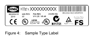
Type Label
The type plate contains the following details:
Product name
Bar code (1D or 2D code)
Part no.
Production year
Hardware revision index (HW Rev.)
Firmware revision index (FW Rev.)
Operating voltage
Mark of conformity
Mounting the F30 in Zone 2
(EC Directive 94/9/EC, ATEX)
The controller is suitable for mounting in zone 2. Refer to the corresponding declaration of conformity available on the HIMA website.
When mounting the device, observe the special conditions specified in the following section.
Specific Conditions X
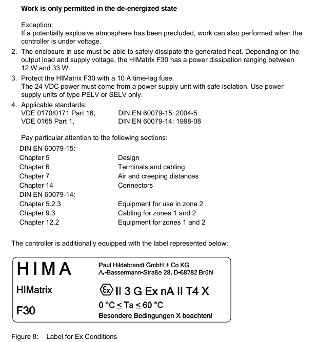
1. Mount the HIMatrix F30 controller in an enclosure that meets the EN 60079-15 requirements and achieves a type of protection of at least IP54, in accordance with EN 60529. Provide the enclosure with the following label:
Work is only permitted in the de-energized state Exception:
If a potentially explosive atmosphere has been precluded, work can also performed when the controller is under voltage.
2. The enclosure in use must be able to safely dissipate the generated heat. Depending on the output load and supply voltage, the HIMatrix F30 has a power dissipation ranging between 12 W and 33 W.
3. Protect the HIMatrix F30 with a 10 A time-lag fuse.
The 24 VDC power must come from a power supply unit with safe isolation. Use power supply units of type PELV or SELV only.
4. Applicable standards:
VDE 0170/0171 Part 16, DIN EN 60079-15: 2004-5
VDE 0165 Part 1, DIN EN 60079-14: 1998-08
Configuration with SILworX
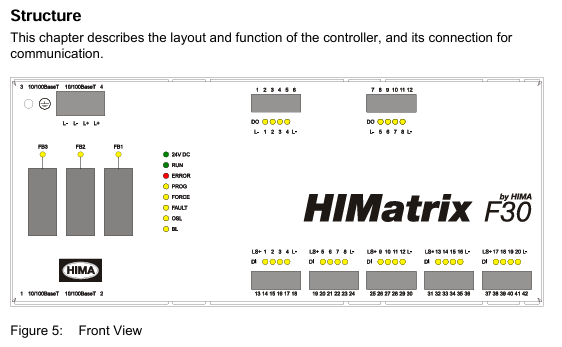
In the Hardware Editor, the controller is represented like a base plate equipped with the following modules:
Processor module (CPU)
Communication module (COM)
Input module (DI 20)
Output module (DO 8)
Double-click the module to open the Detail View with the corresponding tabs. The tabs are used to assign the global variables configured in the user program to the system variables.
Parameters and Error Codes for the Inputs and Outputs
The following tables specify the system parameters that can be read and set for the inputs and outputs, including the corresponding error codes.
In the user program, the error codes can be read using the variables assigned within the logic.
The error codes can also be displayed in SILworX.
Configuration with ELOP II Factory
Configuring the Inputs and Outputs
The signals previously defined in the Signal Editor (Hardware Management) are assigned to the individual channels (inputs and outputs) using ELOP II Factory. Refer to the system manual for compact systems or the online help for more details.
The following chapter describes the system signals used for assigning signals in the controller.
Signals and Error Codes for the Inputs and Outputs
The following tables specify the system signals that can be read and set for the inputs and outputs, including the corresponding error codes.
In the user program, the error codes can be read using the signals assigned within the logic.
The error codes can also be displayed in ELOP II Factory.
Operation
The controller F30 is ready for operation. No specific monitoring is required for the controller.
Handling
Handling of the controller during operation is not required.
Diagnosis
A first diagnosis results from evaluating the LEDs, see Chapter 3.4.1.
The device diagnostic history can also be read using the programming tool.
Maintenance
No maintenance measures are required during normal operation.
If a failure occurs, the defective module or device must be replaced with a module or device of the same type or with a replacement model approved by HIMA.
Only the manufacturer is authorized to repair the device/module.
Faults
If the test harnesses detect safety-critical faults, the module enters the STOP_INVALID state and will remain in this state. This means that the input signals are no longer processed by the device and the outputs switch to the de-energized, safe state. The evaluation of diagnostics provides information on the fault cause.
Maintenance Measures
The following measures are required for the device:
Loading the operating system, if a new version is required
Executing the proof test
Loading the Operating System
HIMA is continuously improving the operating system of the devices.
HIMA recommends to use system downtimes to load a current version of the operating system into the devices.
Refer to the release list to check the consequences of the new operation system version on the system!
The operating system is loaded using the programming tool.
Prior to loading the operating system, the device must be in STOP (displayed in the programming tool). Otherwise, stop the device.
For more information, refer to the programming tool documentation.
Proof Test
HIMatrix devices and modules must be subjected to a proof test in intervals of 10 years.
Decommissioning
Remove the supply voltage to decommission the device. Afterwards pull out the pluggable screw terminal connector blocks for inputs and outputs and the Ethernet cables.
Transport
To avoid mechanical damage, HIMatrix components must be transported in packaging.
Always store HIMatrix components in their original product packaging. This packaging also provides protection against electrostatic discharge. Note that the product packaging alone is not suitable for transport.
Disposal
Industrial customers are responsible for correctly disposing of decommissioned HIMatrix hardware. Upon request, a disposal agreement can be arranged with HIMA.
All materials must be disposed of in an ecologically sound manner.
- OMRON
- ABB
- General Electric
- EMERSON
- Honeywell
- HIMA
- ALSTOM
- Rolls-Royce
- MOTOROLA
- Rockwell
- Siemens
- Woodward
- YOKOGAWA
- FOXBORO
- KOLLMORGEN
- MOOG
- KB
- YAMAHA
- BENDER
- TEKTRONIX
- Westinghouse
- AMAT
- AB
- XYCOM
- Yaskawa
- B&R
- Schneider
- KONGSBERG
- NI
- WATLOW
- ProSoft
- SEW
- ADVANCED
- Reliance
- TRICONEX
- METSO
- MAN
- Advantest
- STUDER
- DANAHER MOTION
- Bently
- Galil
- EATON
- MOLEX
- DEIF
- B&W
- ZYGO
- Aerotech
- DANFOSS
- Beijer
- Moxa
- Rexroth
- Johnson
- WAGO
- TOSHIBA
- BMCM
- SMC
- HITACHI
- HIRSCHMANN
- Application field
- XP POWER
- CTI
- TRICON
- STOBER
- Thinklogical
- Horner Automation
- Meggitt
- Fanuc
- Baldor
- SHINKAWA
- Other Brands
- UniOP
- KUKA
- Iba
- Beckhoff
- ADLINK
75
-
 Rolls Royce H1111.0204 Ship Main Controller
 -
 Basler Electric BE3-32-3AC Reverse Power Relay 9 1376 00 105
 -
 Basler Electric BE3-25-1A1N4 Synch Check Relay 9319100100
 -
 Basler Electric SR4A-2B15B3A Static Voltage Regulator
 -
 Basler Electric SR4A-2B15B3E Static Voltage Regulator
 -
 Basler Electric 9170818100 Solid State Protective Relay
 -
 Basler Electric AEC63-7 Analog Excitation Controller
 -
 Basler Electric 17483 Auxiliary Module
 -
 Basler Electric BE1-59 Over Voltage Relay
 -
 Basler Electric 21600-101 Control Module
 -
 Basler Electric KR2F Generator Voltage Regulator 9056600100
 -
 Basler BE1-CDS Current Differential System
 -
 Basler Electric CBS 212 Current Boost System 9 2650 00 100
 -
 Basler Electric IFM-150 Firing Circuit Chassis
 -
 Basler Electric BE1-60 Voltage Balance Relay C1F A1P D0C3F
 -
 Basler Electric BE1-32R Power Relay A2E D1R A0N0F
 -
Basler Electric BE1-32R Power Relay A2E D1R A0N0F
-
 Basler Electric 8650C80G01 Isolation Transducer PCB Board
 -
 ETEL EA-P2M-300-4/7.5A-0100-01 AccurET Modular 300 Servo Drive
 -
 Basler Electric 87T Transformer Differential Relay
 -
 Basler Electric BE-6868 Power Transformer 5950007559202
 -
 Basler Electric PRS250 Veri-Sync Relay 9088800102
 -
 Basler Electric SCP-250-G-60 VAR Power Factor Controller
 -
 Basler DECS-150 AVR 1NS2V1N1S Voltage Regulator
 -
 Basler UFOV 260A Under Frequency Overvoltage Module
 -
 Basler MOC2 199 Motor Operated Control – Overview and Setup
 -
 Basler BE3-49R-5K5A1 Temperature Relay – Complete Guide
 -
Basler BE 20035 001 Transformer – Technical Data and Installation
-
 Basler BE 02727 001 Transformer – Specifications and Usage
 -
 Basler BE127 Under Voltage Relay – Features and Application Guide
 -
Basler CBS377 Current Boost System – Complete Technical Guide
-
 Basler BE1-87G P/N 9170818100 Differential Relay – In-Depth Specs
 -
Basler BE1-87G Generator Differential Relay – Technical Overview
-
Basler Electric SR4A2B16 SVR Static Voltage Regulator – Complete Guide
-
 Basler Electric 9261500101 Power Supply Module
 -
 Basler Electric AEM-2020 Analog Expansion Module
 -
Basler Electric DGC-2020 Digital Genset Controller 51BRBNEAH001
-
Basler Electric BE1-59N Ground Fault Overvoltage Relay
-
 Basler Electric BE1-59N-A5E-E1L-N0S1F Neutral Overvoltage Relay
 -
Basler Electric MOC2499 Motor Operator Control Potentiometer 9072300430
-
 Basler Electric BE1-50/51M Overcurrent Relay
 -
 Basler Electric 9148100106 MOC3502 Solid State Relay 250VDC 0.25A
 -
 Basler Electric CBS 212 Current Boost System 9265000100
 -
 Basler Electric 10493002 Control Module
 -
Basler BE1-32R D3E E1R A0N1F Power Relay
-
 Basler SR8A2B15B3A Static Voltage Regulator
 -
 Basler IFM-105 Firing Circuit Chassis 9324100105
 -
Basler SR4A2B05B3A Static Voltage Regulator
-
 Basler BE151G1EB6PB0N0F Protective Relay
 -
Basler BE1-59 Electric Over Voltage Relay
-
 Basler 277 Static Programmable Powerline Carrier Channel
 -
 Basler BE1-32R D1E A1P A0N1F Power Relay
 -
Basler SR4A1B07B3A Static Voltage Regulator
-
 Basler Electric BE1-700 Digital Protective Relay
 -
Basler Electric SR8A-2B01B3A Static Voltage Regulator
-
 Basler Electric SR4A-2B01B3E Static Voltage Regulator
 -
 Basler Electric 9017709102 PC Board
 -
Basler Electric SR4A-2B01B3A Static Voltage Regulator
-
 Basler Electric PRS-250 Veri-Sync Relay
 -
 Basler Electric 9066800102 Excitation Support System
 -
Basler Electric BE1-87G Generator Differential Relay 9 1708 18 100
-
 Basler Electric 36T865-2 BE03752001 Power Supply
 -
 Basler Electric M-300 149D940G02 Power Supply
 -
 Basler Electric ACA2040-25GM 4Mp 25Fps Area Scan Camera
 -
 Basler BE1-87G-S1A-A1C-A0N0 Differential Relay
 -
Basler SR8A-2B06B3E Static Regulator SR8A2B06B3E
-
 Basler SCP-210 Frequency Controller 9095400100
 -
 Basler BE1-59-A3E-A1J-N1N3F Overvoltage Relay BE159A3EA1JN1N3F
 -
Basler 9 2011 11 100 Bracket Mounted Terminal Unit
-
Basler 9 1606 00 101 Voltage Regulator
-
 Basler CBS-377 Current Boost System 9109600102
 -
 Basler 8650C72 Exciter Control Module PCB Rev 5
 -
 Basler C2EE1PA0N1F BE1-32R Reverse Power Relay
 -
 ADLINK HPCI-14S12U - Industrial Control Backplane 12PCI Backplane PCI-14S Passive Backplane
 -
-0010.png) ADLINK PCIe-GIE74C - image acquisition card 4-CH GigE Vision PoE+ Frame Grabber
ADLINK PCIe-GIE74C - image acquisition card 4-CH GigE Vision PoE+ Frame Grabber -
-0010_1.png) ADLINK PCI-8164 - control card 4-Axis Advanced Motion Controller Board
ADLINK PCI-8164 - control card 4-Axis Advanced Motion Controller Board -
 ADLINK PCIe-U304 - 4 Port USB3 PCIe Frame Grabbers USB Screw Hole Card
 -
 ADLINK PCI-9112 - Multi-Function Data Acquisition Card DAQ Card
 -
 ADLINK PCI-7432 - 51-12013-0A50 4-CH Isolated Numérique I/O PCI Cartes Digital I/O Card
 -
 ADLINK PCA-6106P3-0C1 REV.C1 - backplane 6-Slot Passive Backplane Board
 -
 ADLINK PCI-7224 - 24-CH Opto-Isolated Digital I/O PCI Board
 -
 ADLINK CPCI-7433R(G) - Digital Input Board Rear I/O CompactPCI Card
 -
 ADLINK EBP-13E4 - 51-46703-0A30 Industrial PC Backplane Passive Backplane
 -
 ADLINK PCIE-HDV62 - Image acquisition card High Definition Video Frame Grabber
 -
 ADLINK EBP-13E4 - 51-46703-0A30 Industrial Backplane Board Passive Backplane
 -
 ADLINK 90111-B1 / CPCI-6770 - PCB CPU MODULE CompactPCI Single Board Computer
 -
 ADLINK PCI-7248 - DATA ACQUISITION PCI CARD 48-CH Parallel Digital I/O Board
 -
 ADLINK PCI-7230 - 51-12003-0a50 board PCI7230 32-CH Isolated Digital I/O Card
 -
 ADLINK PCI2A000CB - 51-20000-0B30 Multi-Function DAQ Card Baseboard
 -
 ADLINK PCI-8134-005 - 4-Axis Motion Controller Card
 -
 ADLINK PCI-7224 - 24-CH Opto-Isolated Digital I/O PCI Card
 -
 ADLINK PCI-7434 - 64-CH Isolated Digital Output Card
 -
 ADLINK PCI-8132 - motion control card 2-Axis Servo & Stepper Controller
 -
 ADLINK PCI-8134 - Motion Controller PCI Card 4-Axis Controller Board
 -
 ADLINK PCI-8164 - Motion Control Card 51-12406-0A40 4-Axis Controller
 -
 ADLINK 51-12001-0C20 - Circuit Board Data Acquisition Interface Module Hardware
 -
 ADLINK NuPR0-840 - industrial control motherboard Full-Size PICMG CPU Board
 -
 ADLINK PCI-7444 - 51-12023-0A10 card 128-CH Isolated Digital Output Board
 -
 ADLINK PCI-1612B - data acquisition card 4-Port RS-232/422/485 Serial Communication Card
 -
 ADLINK PCI-6208V 009 - 8/16-CH 16-Bit Analog Output Cards PCB-I-E-482=6BX3
 -
 ADLINK NUPRO-935A/LV - industrial control motherboard Full-Size PICMG SBC Board
 -
 ADLINK PCI-9114DG - Multi-Function DAQ Card Data Acquisition PCI Card
 -
 ADLINK ACL-7130 - Data acquisition card Isolated Digital I/O Board
 -
 ADLINK ABX-6300D-4E1-BP - board ABX6300D4E1BP Video Interface Expansion Card
 -
 ADLINK CPCI-6940 - CPCI-6940/D1539/M16-0(EA)-000E 6U CompactPCI Processor Board
 -
 ADLINK NuPRO-760 - industrial control motherboard Half-Size PICMG SBC CPU Board
 -
 ADLINK IMB-M42H (G)-0020 - industrial control motherboard LGA1155 Micro-ATX Mainboard
 -
 ADLINK RTV-24 / PCI-MP4S - 51-12519-1C30 4-Channel Real Time Video Capture Board
 -
 ADLINK PCI-8134 - 4-Axis Servo & Stepper Motion Controller Card
 -
 ADLINK MXC-6101D - V.PC000.002.ST.00 Box PC Configurable Embedded Computer
 -
.png) ADLINK PCI-8134A - 51-12421-0A10 Motion Control Card 4-Axis Controller Card
ADLINK PCI-8134A - 51-12421-0A10 Motion Control Card 4-Axis Controller Card -
 ADLINK DIN-100S / DIN-100SA1 - Technology SCSI-II TB 100-PIN Terminal Block Board
 -
.png) ADLINK DIN-812M001 / DIN812M001 - 51-14034-0A1 51140340A1 Terminal Module Breakout Interface
ADLINK DIN-812M001 / DIN812M001 - 51-14034-0A1 51140340A1 Terminal Module Breakout Interface -
_1.png) ADLINK PCI-8164 - Servo motion control 4-Axis Advanced Controller Card
ADLINK PCI-8164 - Servo motion control 4-Axis Advanced Controller Card -
 ADLINK PCIe-GIE64 - Acquisition card GigE Vision PoE+ Frame Grabber
 -
 ADLINK M-302 - Industrial control motherboard ATX PC Board Mainboard
 -
 ADLINK PCI-8134 - Motion Controller PCI Card 4-Axis Controller Board
 -
 ADLINK PCI-RTV24 - Image capture card Analog Video Frame Grabber
 -
 ADLINK PCI-8102 - Motion control card 2-Axis Servo & Stepper Controller Board
 -
 ADLINK PCI-9112 REV.B1 - Card Multi-Function Data Acquisition Card
 -
 ADLINK HSI-DI32-M-N / HSL-TB32-M-DIN - Discrete I/O MODULE Distributed Automation Module System
 -
 ADLINK PCI-7296 - IO card REV.A3 96-CH Parallel Digital I/O Card
 -
-0020.png) ADLINK DIN-814P-A4 / 814Y - terminal board Motion Control Interface Block
ADLINK DIN-814P-A4 / 814Y - terminal board Motion Control Interface Block -
 ADLINK DIN-814P-A4 - 51-14056-0A10 PCB-I-E-2736=ZA01 Screw Terminal Board Breakout
 -
 ADLINK M-322 - motherboard Industrial Control Computer Mainboard
 -
 ADLINK NUPRO-406 REV:B1 - industrial control motherboard Full-Size PICMG CPU Board
 -
 ADLINK AMP-204C - card DSP-Based 4-Axis Advanced Pulse-Train Controller
 -
 ADLINK HPCI14S REV.B1 - industrial computer baseboard 14-Slot Passive Backplane
+86-153-9626-8993
WeChat
Contact

Whatsapp

After years of experience, it has developed into a group enterprise entity integrating equipment, industrial, chemical, petroleum equipment, electricity and other products trade and services.
XING-Automation


Product
Copyright © 2026 XING Group All Rights Reserved .