SIEMENS SIMATIC S7 300/400 operates MICROMASTER 4 (MM4) frequency converter through Profibus DP
Set value transmission: Loop the speed set value in the form of percentages from * * -100% to+100% * *, and any changes will take effect in real-time.
Status feedback: Output signals such as motor rotation direction (O-Right/O-Left), actual frequency (O-Actual_frequency, range -100% to+100%), and shutdown status (O-STOP).
Technical data area: Enter other parameters that are not quick debugging, support sub parameters (sub parameter 0 is the first, such as data [2] indicating the presence of sub parameters 0 and 1), and match the data type of the parameters.
5.2.2 Parameter input method
Operation steps for input method
Method 1: The frequency converter has been debugged and set to I2 Enable=0 and I2 Enable QC=1;
2. Set IOUR_Parameters=1 to start data reading;
3. O-Data_transfer_running=1 indicates that the transfer is in progress, and after completion, IOUR_Parameters will automatically clear 0.
Method 2: 1. Enter parameters directly on the OP interface (only display the parameters that need to be changed);
2. Use initial values for other parameters and support leaving the DB list empty (for easy OP indirect addressing).
5.2.3 Automatic Debugging Steps
Restore MM4 to factory settings.
Perform quick debugging (transfer motor data area parameters).
Transmission technology data area parameters.
Save the parameters to the EEPROM of MM4.
After debugging is completed, perform motor identification (ensuring that there are no errors during debugging and the motor is in a cold state).
5.3 Parameter transmission mechanism
Communication method: Based on PKW communication, it supports three parallel parameter read/write requests (Job_1~Job_3), which are executed in the order of Job_1 → Job_2 → Job_3.
Request block structure (taking Job_1 as an example):
|Parameter Name | Type | Initial Value | Description|
|Job_1. Parameter-N | INT | 0 | Target parameter number (e.g. 1002 represents fixed frequency 2)|
|Job_1. Index | INT | 0 | Sub parameter number (set 0 when there is no sub parameter, set the last sub parameter number when there are multiple sub parameters)|
|Job_1. Identifier | Byte | B # 16 # 0 | Operation type: 1=Read single parameter, 2=Write RAM, 3=Write EEPROM, 11=Read multiple sub parameters, etc|
|Job_1. Value_2~2 | DINT | L # 0 | Transferred parameter values (used as needed, such as using only Value_0 for a single parameter)|
Control signal: Job.RWRequest_1~3 are request trigger signals (user set 1 to start, clear 0 after FB is completed); Data_fault.Job.RWRequest_1~3 are error signals corresponding to the requests.
5.4 Diagnostic mechanism
5.4.1 Classification of Error Sources
Malfunctions/alarms of MM4 (such as overcurrent and overvoltage).
Fault of standard FC (SFC14/SFC15).
The functional block itself is malfunctioning.
Parameter transmission and automatic debugging errors.
5.4.2 Key diagnostic signals and displays
Parameter Name Type Direction Description
When there is an alarm for O-Warning BOOL OUT, it is 1
O-Fault BOOL OUT MM4 fault is 1 (excluding data errors)
Resetting signal: clearing MM4 fault and data error display, interrupting debugging process (without interrupting parameter transmission)
Data_fault.Nr. INT STAT error number (e.g. 0=illegal parameter number, 17=request execution not allowed in running state)
Data_fault.DP_Add_info HEX STAT DP error details (e.g. 8090=no module specified address, corresponding to SFC14/SFC15 error)
Error code description
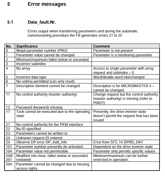
6.1 Data_fault.Nr. (Parameter transmission and debugging errors)
Error Number Meaning Remarks
0 Illegal Parameter Number (PNU) parameter does not exist in MM4
The parameter value cannot be modified. This parameter is a monitoring type parameter and can only be read
17. Due to operational status, the task cannot be executed. The current MM4 status does not support this request (such as changing motor data during operation)
25 DP error needs to be viewed in conjunction with Data_fault.DP_Add_info for details
Parameter number 1001 is currently not activated and depends on the running status of MM4. It can be operated after activation
6.2 Data_fault.DP_Add_info (DP Error Supplement)
Meaning of Error Code (W # 16 #)
8090 specifies logical address without configuration module
80A0 recognized access error while accessing I/O
The target range length of 80B0 does not match the network data length configured in Step 7
6.3 Data_fault.Fault_Commission
Error Number Meaning Remarks
1001 DP error needs to be investigated for Profibus DP connection and address configuration
1002 automatic debugging data error parameter DB has errors (such as parameter values exceeding the range)
1007 MM4 model incorrectly configured MM4 model does not match the actual connected device
Functional Block Technical Data
Project specifications
Block type FB
Block Name MM4
Generate language STL
Local data 36 bytes
MC7 code length 3166 bytes
Load memory requirement 4244 bytes
Working memory requirement 3202 bytes

- ABB
- General Electric
- EMERSON
- Honeywell
- HIMA
- ALSTOM
- Rolls-Royce
- MOTOROLA
- Rockwell
- Siemens
- Woodward
- YOKOGAWA
- FOXBORO
- KOLLMORGEN
- MOOG
- KB
- YAMAHA
- BENDER
- TEKTRONIX
- Westinghouse
- AMAT
- AB
- XYCOM
- Yaskawa
- B&R
- Schneider
- Kongsberg
- NI
- WATLOW
- ProSoft
- SEW
- ADVANCED
- Reliance
- TRICONEX
- METSO
- MAN
- Advantest
- STUDER
- KONGSBERG
- DANAHER MOTION
- Bently
- Galil
- EATON
- MOLEX
- Triconex
- DEIF
- B&W
- ZYGO
- Aerotech
- DANFOSS
- Beijer
- Moxa
- Rexroth
- Johnson
- WAGO
- TOSHIBA
- BMCM
- SMC
- HITACHI
- HIRSCHMANN
- Application field
- XP POWER
- CTI
- TRICON
- STOBER
- Thinklogical
- Horner Automation
- Meggitt
- Fanuc
- Baldor


