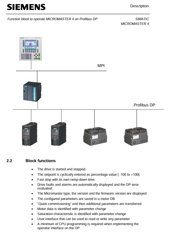
SIEMENS SIMATIC S7 300/400 operates MICROMASTER 4 (MM4) frequency converter through Profibus DP
Set value transmission: Loop the speed set value in the form of percentages from * * -100% to+100% * *, and any changes will take effect in real-time.
Status feedback: Output signals such as motor rotation direction (O-Right/O-Left), actual frequency (O-Actual_frequency, range -100% to+100%), and shutdown status (O-STOP).
SIEMENS SIMATIC S7 300/400 operates MICROMASTER 4 (MM4) frequency converter through Profibus DP
Core purpose and value of functional blocks
Inverter control
Implement motor start stop: supports regular start stop (dependent on P1120 ramp up time, P1121 ramp down time) and quick stop (dependent on P1135 OFF3 ramp down time).
Set value transmission: Loop the speed set value in the form of percentages from * * -100% to+100% * *, and any changes will take effect in real-time.
Status feedback: Output signals such as motor rotation direction (O-Right/O-Left), actual frequency (O-Actual_frequency, range -100% to+100%), and shutdown status (O-STOP).
Automatic debugging
Batch/Replacement Scenario Adaptation: When debugging multiple MM4 units in bulk or replacing a single faulty unit, there is no need for PG/PC or professional debugging software. The PLC can automatically complete the parameter configuration of the new MM4.
Simplified debugging process: including quick debugging (P0010=1), motor recognition (requires motor cold state), and saturation characteristic recognition (only supported by MM440).
parameter management
Full parameter read and write: Read and write all parameters of MM4 through PKW communication, and the OP (operation panel) only supports parameter reading.
Parameter backup: Store the debugged parameters in the PLC's parameter DB (data block) for easy recovery in the future.
Diagnostic function
Multi dimensional error monitoring: covering MM4 faults/alarms, Profibus DP errors, parameter transmission errors, and automatic debugging errors.
Historical data recording: stores the latest and historical fault/alarm information (such as the fault codes and values of the last 3 faults), supports fault reset (I_RESET_Corr).
Scope and Limitations of Application
3.1 Applicable Equipment
Equipment type, specific model/specification
MM4 frequency converter MM411 V1.10, MM420 V1.17, MM430 V2.00, MM440 V2.05
Controller SIMATIC S7 300 (CPU 313-2DP and above) S7 400、C7、SINUMERIK
3.2 Not Applicable Devices and Limitations
Not applicable to controllers: SIMATIC S7 200, SIMATIC S5.
Function limitation: The system does not monitor whether the startup signal (I_Enable) meets safety conditions, and users need to provide additional protection in the program.

Installation and configuration process
4.1 Scenario without Drive ES Basic and Starter
Hardware configuration: Set the Profibus DP address of MM4 (no need to reset to factory settings).
HW Config operation:
Start HW Config in Step 7 and configure PLC hardware.
Select "MICROMASTER 4" in the "PROFIBUS-DP/SIMOVERT Catalog" and specify the DP address.
Select slot 1 and configure PPO type as PPO1 (4 PKW+2 PZD).
Program loading:
Save and compile HW Config, download to PLC module.
Copy the program blocks and symbol table from the functional block example to the user program, adapt them, load them into the PLC, and start them.
Debugging startup: Call the MM4 diagnostic interface of OP to troubleshoot DP errors, enter the debugging interface to enter motor data, start automatic debugging (set I2 Enable=0, I2 Enable QC=1, IOU_ Parameters=1), and execute motor recognition after completion.
4.2 Scenarios with Drive ES Basic and Starter
Hardware configuration: Follow step 1 of section 4.1 to set the DP address of MM4.
HW Config operation:
Configure PLC and MM4, select the corresponding MM4 version (refer to the equipment nameplate, such as "A01/2.05" corresponding to version 2.0x).
Pre allocate PPO type as PPO1 (PKW+PZD-2/2), fill in the I/O address of MM4 (PKW starting address, PZD address is PKW address+8).
Program and OP adaptation:
Load the program block and symbol table in step 3 of section 4.1.
Install OP project and adapt to "MM4" and "ParameterDB" text lists.
Debugging startup: The first debugging can be completed through Starter, and the parameters can be entered into the parameter DB; or the OP debugging interface can be directly called, and the subsequent process is the same as step 4 in 4.1.
Detailed explanation of key functions
5.1 Definition of Control and Feedback Signals
Parameter Name Type Direction Unit/Range Description
The starting I/O address of the PKW area configured in the I-Address INT IN - HW Config
I-Enable BOOL IN - Variable frequency drive enable signal, can only be set when O-Drive-ready=1
I-Fast-STOP BOOL IN - Fast Shutdown Signal: 0=Fast Shutdown (using P1135), 1=Normal Shutdown (default can be set to 1)
Setpoint INT IN -100~+100 speed setting value (percentage)
Actual operating frequency INT OUT -100~+100 (percentage)
O-Drive-ready BOOL OUT - Inverter ready signal: must meet the requirements of "shutdown, I-Fast-STOP=1, no faults, no debugging in progress"
O-Fault BOOL OUT - MM4 fault signal (excluding data transmission errors)
O-Data_ error BOOL OUT - Parameter transmission/automatic debugging error signal
IOU_ Parameters BOOL IN/OUT - Start automatic debugging signal (user set 1 to start, clear 0 after FB is completed)
5.2 Automatic Debugging Process
5.2.1 Parameter DB adaptation
Motor data area: Enter the required parameters for quick debugging (P0010=1), using motor dataset 0 by default; Multiple parameter DBs need to be created for multiple datasets, which can be specified through Z_Sotor_data_SBNr.
- ABB
- General Electric
- EMERSON
- Honeywell
- HIMA
- ALSTOM
- Rolls-Royce
- MOTOROLA
- Rockwell
- Siemens
- Woodward
- YOKOGAWA
- FOXBORO
- KOLLMORGEN
- MOOG
- KB
- YAMAHA
- BENDER
- TEKTRONIX
- Westinghouse
- AMAT
- AB
- XYCOM
- Yaskawa
- B&R
- Schneider
- Kongsberg
- NI
- WATLOW
- ProSoft
- SEW
- ADVANCED
- Reliance
- TRICONEX
- METSO
- MAN
- Advantest
- STUDER
- KONGSBERG
- DANAHER MOTION
- Bently
- Galil
- EATON
- MOLEX
- Triconex
- DEIF
- B&W
- ZYGO
- Aerotech
- DANFOSS
- Beijer
- Moxa
- Rexroth
- Johnson
- WAGO
- TOSHIBA
- BMCM
- SMC
- HITACHI
- HIRSCHMANN
- Application field
- XP POWER
- CTI
- TRICON
- STOBER
- Thinklogical
- Horner Automation
- Meggitt
- Fanuc
- Baldor


