
How to install GE V7768/V7769 hardware?
How to install GE V7768/V7769 hardware?
Basic information
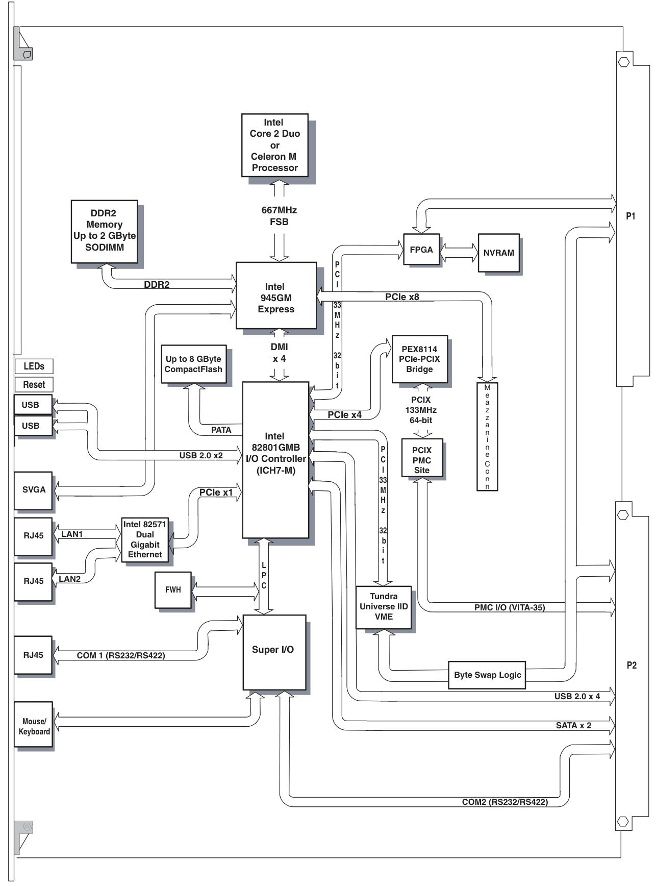
V7768/V7769 is a product launched by GE based on Intel ® Core ™ The VME single board computer (SBC) with Duo processor adopts the dual slot, passive cooling VME Eurocard external specification, which complies with the current version of the EU RoHS directive (2002/95/EC). V7768 is equipped with Intel ® Core ™ 2 Duo or Celeron ® The V7769 is a fully functional SBC equipped with an Intel Core 2 Duo processor, both of which use Intel's 945GM chipset and ICH7-M I/O controller hub. When paired with a Celeron M processor, the front-end bus of the 945GM chipset is 533 MHz, and when paired with a Core 2 Duo processor, it is 667 MHz. Both comply with the VMEbus specification VITA 1-1994 and have transparent PCI to VME bridging capabilities.
Main functions and features
desktop function
Processor and Memory: V7768 is equipped with Intel Core 2 Duo or Celeron M processors, while V7769 is equipped with Intel Core 2 Duo processors; In terms of memory, the maximum capacity is 2.0GB DDR2 SDRAM (one SODIMM).
Display and Interface: Equipped with SVGA port (front I/O), dual Gigabit Ethernet (GbE) (front I/O), one RS232/422 COM port (front I/O), one RS232/422 COM support (rear I/O), two USB 2.0 ports (front I/O), four USB 2.0 supports (rear I/O), supports two SATA connections (rear I/O), V7769 can choose a 2.5-inch SATA hard drive, V7769 has unique dual SAS connectors (front I/O), etc.
Other: including real-time clock/calendar, front panel reset switch, PS/2 keyboard/mouse connection (front I/O), onboard parallel connector, etc.
Embedded functionality
Storage and Expansion: Supports remote boot from the front panel, up to 8GB bootable CompactFlash (optional), PMC site with PCI-X functionality (with VITA 35 P2 I/O, factory installed on V7768 and V7769 motherboards), etc.
Compatibility and Storage: Complies with VITA 1-1994 standard and supports byte swapping, 32KB NVRAM, optional watchdog timer with reset function, PMC expansion site.
Applicable scenarios: Suitable for various application scenarios such as telecommunications, simulation, instrumentation, industrial control, process control and monitoring, factory automation, automatic testing systems, data acquisition systems, etc.
Installation and setup
Unboxing and hardware setup
After opening the box, it is necessary to check whether the items have been damaged during transportation and pay attention to electrostatic protection.
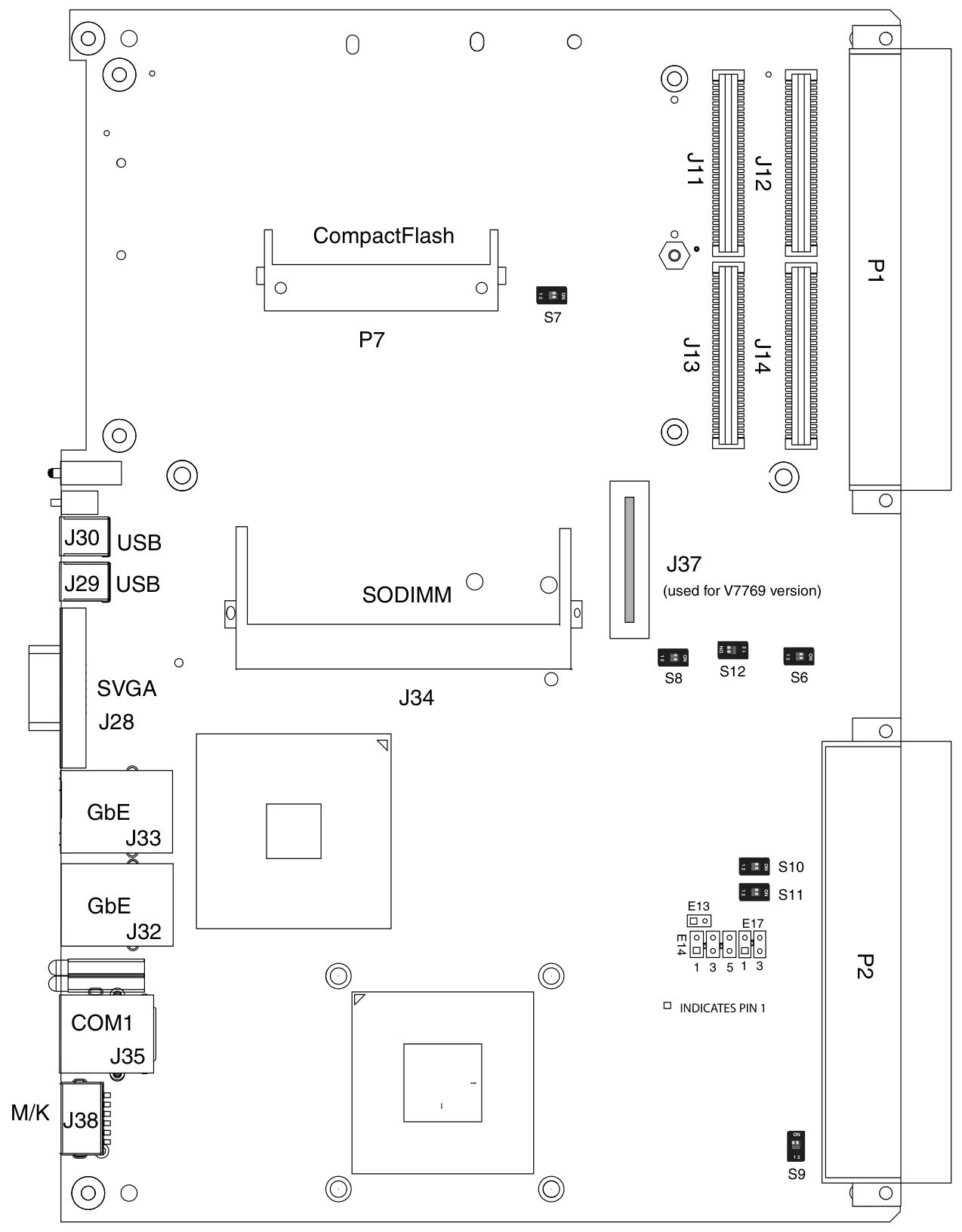
Hardware settings involve various connectors, joints, and switches, such as VME interface connector (P1), USB 2.0 and other related connectors (P2), CompactFlash slot (P7), etc. Users can configure some jumper wires according to their needs, and factory configured jumper wires should not be modified by users. Modifying jumper wires that are not user configured will void the warranty and may damage the equipment.
Installation steps
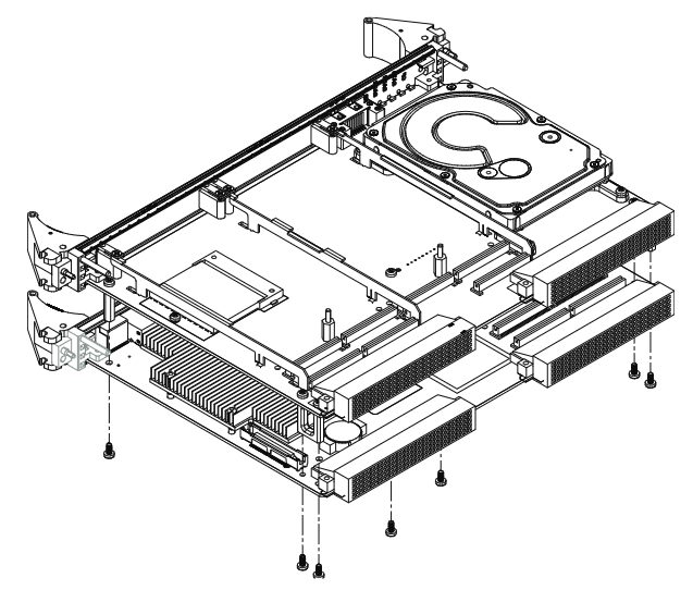
If using PMC module, connect it to V7768/V7769 before installing the motherboard, and refer to the product manual of PMC module for configuration and settings.
Insert V7768/V7769 into the system controller or peripheral slot of the VME chassis, ensuring proper alignment and secure installation.
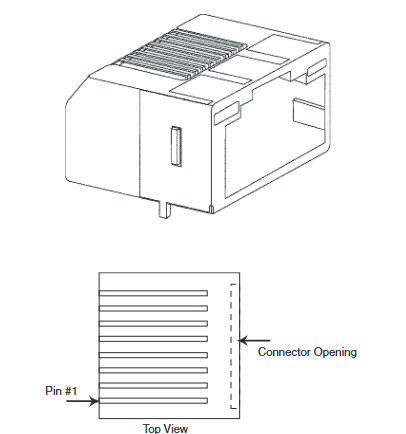
The required peripherals can be accessed from the front panel or rear I/O, and each connector is clearly labeled. The detailed pin distribution can be found in Appendix A.
If the system is not pre configured, a keyboard and mouse need to be connected.
V7768 has an optional onboard CompactFlash disk, please refer to Chapter 3 "Embedded PC/RTOS Functions" for configuration details.
If an external driver module is installed, the BIOS setup program must be used to configure the driver type. Refer to Appendix B for proper system configuration.
If there is a driver module, install the operating system according to the manufacturer's instructions.
BIOS settings
Entering the BIOS setup interface: Pressing the DEL key will enter the BIOS setup utility during system startup, which includes multiple menu options for detailed system configuration.
Main Menu: displays system information such as BIOS version, processor type, clock speed, and supports setting system clock and calendar. The configurable options in the menu are displayed in blue, while the options displayed in gray are not configurable. After selecting an item, its brief description will be displayed on the right side.
Advanced BIOS Setup Menu: Used to configure CPU settings, IDE bus, other external devices, and internal drives. Caution should be exercised during operation, as incorrect settings may lead to system malfunctions. If there is a problem after the change, you can select "Load Failed Safe Defaults" from the Exit menu and restart the system; If a system malfunction prevents access to the BIOS interface, you can refer to the "Installation and Setup" chapter to clear the CMOS.
PCI/PnP Setup Menu: Used to control internal peripheral cards and various interrupts, as well as set the system's plug and play functionality. Similarly, incorrect settings may cause system failures, and the solution is similar to the advanced BIOS settings menu.
Boot Setup Menu: You can set the priority of starting the device, including starting from a remote network. If the installed driver is not displayed in the menu, check the hardware installation. In addition, basic system related behaviors can be set, such as PS/2 mouse support and whether to use "Quick Boot".
Security Setup Menu: Provides password settings for both Supervisor and User. If two passwords are used simultaneously, the administrator password must be set first. The system can be configured to require the user to enter a password every time it starts or enters ezPORT settings. When you forget your password, you need to clear the NVRAM and reconfigure it. Please refer to the "Installation and Setup" chapter for specific instructions.
Chipset Setup Menu: Used to select various options for the chipset in the system, such as CPU configuration and north-south bridge configuration. Due to the fact that chipset settings are processor related, extra caution should be taken when changing settings, following troubleshooting methods similar to those in the above menu.
Exit Menu: You can choose to save or discard changes and exit BIOS settings. If the previous BIOS settings cause system failure, you can select 'Load Failed Safe Defaults' from this menu and continue restarting.
First Boot Menu: Pressing the F11 key will enter this menu during startup, allowing users to choose to boot from a specific device at once, such as selecting ATAPI CD-ROM Drive when installing the operating system from a CD. This selection is only valid for the current boot. If you are unable to access this menu, you can disable QuickBoot Mode in the Main BIOS settings screen, save the changes, and try again.
- OMRON
- ABB
- General Electric
- EMERSON
- Honeywell
- HIMA
- ALSTOM
- Rolls-Royce
- MOTOROLA
- Rockwell
- Siemens
- Woodward
- YOKOGAWA
- FOXBORO
- KOLLMORGEN
- MOOG
- KB
- YAMAHA
- BENDER
- TEKTRONIX
- Westinghouse
- AMAT
- AB
- XYCOM
- Yaskawa
- B&R
- Schneider
- KONGSBERG
- NI
- WATLOW
- ProSoft
- SEW
- ADVANCED
- Reliance
- TRICONEX
- METSO
- MAN
- Advantest
- STUDER
- DANAHER MOTION
- Bently
- Galil
- EATON
- MOLEX
- DEIF
- B&W
- ZYGO
- Aerotech
- DANFOSS
- Beijer
- Moxa
- Rexroth
- Johnson
- WAGO
- TOSHIBA
- BMCM
- SMC
- HITACHI
- HIRSCHMANN
- Application field
- XP POWER
- CTI
- TRICON
- STOBER
- Thinklogical
- Horner Automation
- Meggitt
- Fanuc
- Baldor
- SHINKAWA
- Other Brands
- UniOP
- KUKA
- Iba
- Beckhoff
- ADLINK
-
 ETEL DSCDL332-131C-000A Servo Control Board
 -
 ETEL DSCDP324-322F-000C Dual Motor Driver
 -
 ETEL EA-P2M-400-10/20A Position Controller
 -
 ETEL DSC2P121 and DSO-HIO33 Servo Amplifier Set
 -
 ETEL EA-P2M-400-15/40A AccurET Drive
 -
 ETEL EA-P2M-300-07/15A Position Controller
 -
 ETEL EA-P2M-048-05/10A-0100-01 Servo Drive
 -
 ETEL EA-S0M-300-40/80A Servo Drive Guide
 -
 ETEL DSB2P131-111E-000H Digital Servo Amplifier
 -
 ETEL DSCDP334-421-000 Servo Drive Guide
 -
ETEL EA-S0M-300-40 80A-0000-00 Motion Control Module
-
 ETEL UltimET Light Motion Controller EU-LGP-0-0-1000-01 Multi-Axis
 -
 ETEL DSO-RAC601-029 Controller Rack
 -
ETEL DSMAX212-121C-000C Board
-
 ETEL DSCDL132-212B-000C Position Controller
 -
 ETEL TMB0291-050-3TDS-E82 Torque Motor
 -
 ETEL DSMAX212-121-000 Board
 -
 ETEL DSB2P131-111E-000H Digital Servo Controller Amplifier Unit
 -
 ETEL DSB 2S 124-211E-000H Digital Servo Amplifier
 -
 ETEL AccurET EA-P2M-300-4/7.5A-0100-01 Modular Position Controller
 -
 Beckwith Electric M-6280A Digital Capacitor Bank Control
 -
 Beckwith M-2355B Adapter Panel with M-2001C-6SL Tapchanger Control
 -
 Beckwith M-0359 Syncrocloser MOD512
 -
Beckwith Electric M-2001C-6ELFA Tap Changer Controller
-
 Beckwith M-3311A 4-Coil Transformer Protection Relay
 -
 Beckwith M-0124 Terminal Board Adapter Plate Guide
 -
 Beckwith Pride M-0296C 3-Phase Programmable Relay
 -
 Beckwith M-0388 Syncrocloser Check Relay Guide
 -
 Beckwith M-0170A AC Current Relay Guide
 -
Beckwith M-3311 Transformer Protection Relay Guide
-
Beckwith Electric M3310 Integrated Transformer Protection Panel
-
 Beckwith M-0145 First Customer Protector
 -
Beckwith M-0170A AC Current Relay
-
 Beckwith PRIDE M-0296C 3 Phase Programmable Relay
 -
 Beckwith Pride M-0296b 3-Phase Programmable Relay
 -
Beckwith M-0245C High Speed Sync-Check Relay Guide
-
 Beckwith M-0115A AC Parallel Balancing Module
 -
Beckwith M-0389 Voltage Verifier Relay
-
Beckwith M-0115A Parallel Balancing Module
-
 Beckwith M-0389 Voltage Verifier
 -
 Beckwith PRIDE M-0420 Multifunction Relay Protection Module 48VDC
 -
 Beckwith Electric M-3430 Generator Protection Relay
 -
 Beckwith Electric M-0067E Tapchanger Control
 -
 Beckwith Electric M-0420 Multifunction Relay
 -
Beckwith Electric M-2001D-6L4S20C0S0X Tap Changer Control
-
 Beckwith Electric M3425A-STD1 Generator Protection Relay
 -
Beckwith Electric M-0245C High Speed Sync-Check Relay
-
Beckwith Electric M-3520 Intertie Protection Relay Guide
-
Beckwith Electric M-2001C-6SL Tap Changer Control
-
Beckwith Electric M-2001C Tap Changer Control Guide
-
Beckwith 35-12-635 Generator Protection Keypad Interface
-
Beckwith Electric P-2216 Generator Protection Main Board
-
 Beckwith Electric M-2293 Tap Changer Control Guide
 -
 Beckwith M-4272-6AB1EH0 Integrated Synchronizing Motor Bus Transfer
 -
Beckwith Electric M-4272 Motor Bus Transfer 60-140V 50/60Hz
-
Beckwith Electric M-2001B TapChanger Control
-
Beckwith Electric M-0193B Synchrocloser Unit
-
Beckwith Electric M-0115A AC Parallel Balancing Module
-
Beckwith Electric M-0169A Current Transformer
-
 Beckwith Electric P-1939 Generator Protection Annunciator Panel
 -
Beckwith Electric M-3311A Transformer Protection Relay Guide
-
Beckwith Electric M-0245B High Speed Sync-Check Relay
-
Beckwith Electric M3420 Generator Protection Relay
-
 Beckwith M-0193B Syncrocloser Unit
 -
 Beckwith Electric M-520 Intertie Protection Relay
 -
 Beckwith Electric M-3425A Generator Protection Relay
 -
Beckwith M-3425 Integrated Generator Protection Relay
-
Beckwith M-0115A Parallel Balancing Module
-
Beckwith Electric M-4272 Integrated Synchronizing Motor Bus Transfer
-
Beckwith Electric M-3420 Generator Protection System
-
Beckwith M-0193 Syncrocloser Unit
-
 Basler Electric DECS-250-CN1SN1N Digital Excitation Control System
 -
 Basler Electric BE1-700 E0N2X1N Digital Protective Relay
 -
 Basler Electric SR4A-2B15B3A Static Voltage Regulator 120VAC 50/60Hz
 -
 Basler Electric 9261402111 PCB Control Board 9346000033
 -
 Basler Electric BE28053-002 Transformer BE28053002
 -
 Basler Electric BE3-25A Auto Synchronizer B1D Sync Module
 -
 Basler Electric BE3-GPR Generator Protective Relay
 -
 Basler Electric SCP-250-G-60 VAR Power Factor Controller 9 1100 00 109
 -
 Basler Electric BE3-32-1S1N1 Reverse Power Relay 277V 5A
 -
 Basler Electric ACA1300-60GM Area Scan Camera 106200-17
 -
 Basler Electric UFOV 260 A Protection Module Specs
 -
 Basler Electric BE03303001 Control Module
 -
Basler Electric BE3-GPR-P1BVSF Generator Protective Relay
-
 Basler Electric BE1-87G Solid State Protective Relay Guide
 -
 BASLER ELECTRIC BE1-60 VOLTAGE BALANCE RELAY T176884
 -
 Basler Electric BE1-32R Protective Relay
 -
 Basler Electric 9022900-103 Transformer 6-7VA 60Hz
 -
 Basler Electric BE1-59-A4E-E1K-B1S3F Overvoltage Relay
 -
 Basler Electric KR2FF-M Voltage Regulator 9 1163 00 103
 -
 Basler Electric UFOV 260 A Protective Module
 -
 Basler Electric PCB Assembly 9059701100 919620
 -
 Basler Electric SR8A2B01A3E Static Voltage Regulator
 -
 Basler Electric SSR125-12 Static Voltage Regulator 9185900102
 -
 Basler Electric SSR 63-12 Static Voltage Regulator 600VAC
 -
 Basler Electric BE1-60 Solid State Protective Relay
 -
 Basler Electric BE3-47N/27-3A4N2 Voltage Relay 9320400101
 -
 Basler Electric BE1-59 Over Voltage Relay
 -
 Basler Electric DECS100-B15 Automatic Voltage Regulator
 -
 Basler Electric PRS250 Veri-Sync Relay 9088800102
 -
Basler Electric BE25927001 Current Transformer 1:34 Amp
-
Basler Electric 9170818100 Generator Differential Relay
-
 Basler Electric BE1-59N Solid State Ground Fault Overvoltage Relay
 -
 Basler Electric 1783 DC Current Transformer Coil 1200:5A
 -
Basler Electric BE1-67 Ground Directional Overcurrent Relay
-
 Basler Electric UFOV-260A Underfrequency Overvoltage Module
 -
 Basler Electric BE10493001 Control Module
 -
Basler Electric SSR125-12 Static Voltage Regulator Guide
-
 Basler Electric BE1810/U-2 Solid State Frequency Relay Guide
 -
 Basler Electric 9105100106 UFOV-250A Protector Guide
 -
 Basler Electric MOC2199 9072300-335 Relay Module Guide
 -
 Basler Electric 9289902106 Circuit Board
 -
Basler Electric BE1-32R Protective Relay A1E E1P BOS1P
-
 Basler Electric RAL6144-16GM GigE Line Scan Camera with Lens
 -
 Basler Electric BE3-49R-5I5A1 Temperature Relay
 -
 Basler Electric BE1-32R Power Relay B3E E1R A0N1F
 -
 Basler Electric SR4A2B06B3A Static Voltage Regulator Features
 -
 Basler Electric 9121000106 Manual Voltage Control MVC Guide
 -
Basler Electric SR32A-2B15B3E Static Voltage Regulator
-
 Basler Electric SR4A2B06B3A Static Voltage Regulator Guide
 -
Basler Electric 801A193F02 Hammond Transformer Module
-
 Basler Electric BE1-24 Volts Per Hertz Relay A1E F1J D1S0F
 -
 Basler Electric AEC63-7 Analog Excitation Controller 220-277V
 -
Basler Electric BE132R Power Relay T245579
-
 Basler Electric MVC 108 Manual Voltage Control 90 37000 102
 -
 Basler Electric 9022900-103 Control Transformer 6-7VA 60Hz
 -
 Basler Electric BE1-79M Plug Adapter 9170111102
 -
 Basler Electric 9 2007 00 100 Current Boost System CBS 305


