
Xycom Automation XT1502T Pro Face LAT PANEL INDUSTRIAL MONITOR
The XT1502 flat panel monitor delivers crisp, bright text and graphics with a low current draw, and it fits into panels that CRTs cannot.
The XT1502 is self-contained, requiring only to be panel mounted in an appropriate enclosure and connected to 120/240 VAC and VGA source
To keep the temperature in range, the cooling air at the base of the system must not exceed the maximum temperature specification (see pg. 1-4).
Allocate proper spacing between internal components installed in the enclosure.
• Place any fans or blowers close to the heat-generating devices.
If using a fan, make sure that outside air is not brought inside the enclosure unless a fabric or other reliable filter is used.
This filtration prevents conductive particles or other harmful contaminants from entering the enclosure.
• Do not place incoming power line devices (such as isolation or constant voltage transformers, local power disconnects, and surge suppressers) near the system.
The proper location of incoming line devices keeps power wire runs as short as possible and minimizes electrical noise transmitted to the unit.
• Avoid overloading the supply circuit
Back Light Replacement Procedure
After 50,000 hours of use, the two lamps used for LCD back lighting may become dim or burn out. You may return the monitor to Xycom for lamp replacement or you can order new lamps and follow the procedure below to install them.
You can perform the lamp replacement procedure without removing the monitor from the NEMA enclosure where it is mounted, but you should do this only in a clean environment.
Otherwise, the procedure is better performed at a service bench.
6. Look in the hole where the lamp is presently installed and note the small black locking tab on the front side of each hole. With a small slotted screwdriver, depress the tab while carefully pulling on the wires and slide the lamps outward.
Discard the old lamps.4-1 VGA Input Connector Pin Out

- OMRON
- ABB
- General Electric
- EMERSON
- Honeywell
- HIMA
- ALSTOM
- Rolls-Royce
- MOTOROLA
- Rockwell
- Siemens
- Woodward
- YOKOGAWA
- FOXBORO
- KOLLMORGEN
- MOOG
- KB
- YAMAHA
- BENDER
- TEKTRONIX
- Westinghouse
- AMAT
- AB
- XYCOM
- Yaskawa
- B&R
- Schneider
- KONGSBERG
- NI
- WATLOW
- ProSoft
- SEW
- ADVANCED
- Reliance
- TRICONEX
- METSO
- MAN
- Advantest
- STUDER
- DANAHER MOTION
- Bently
- Galil
- EATON
- MOLEX
- DEIF
- B&W
- ZYGO
- Aerotech
- DANFOSS
- Beijer
- Moxa
- Rexroth
- Johnson
- WAGO
- TOSHIBA
- BMCM
- SMC
- HITACHI
- HIRSCHMANN
- Application field
- XP POWER
- CTI
- TRICON
- STOBER
- Thinklogical
- Horner Automation
- Meggitt
- Fanuc
- Baldor
- SHINKAWA
- Other Brands
- UniOP
- KUKA
- Iba
-
 Allen-Bradley 193-EC2AB E3 Plus Overload Relay
 -
 GE DS200TCTGG1AFF Turbine Control Board
 -
 Westinghouse 1C31170G02 Ovation Module
 -
 Mitsubishi A2ACPU21 Programmable Controller Review
 -
 710-95045-AD PLC I/O Operation Console Cable
 -
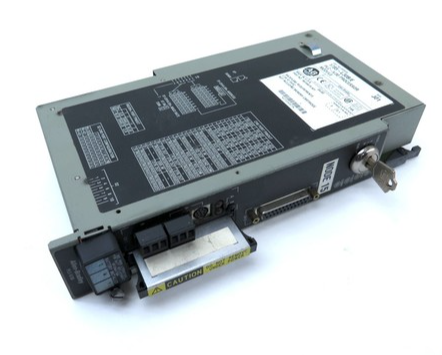
 Allen-Bradley 1785-L11B PLC-5 Processor Specifications
 -
 BEMAC UST-202-D 1307D V08B2 Circuit Board
 -
 Pilz 312070 PSSu H PLC1 FS Safety Module
 -
 Keyence QS-MB1 Safety Network Module Overview
 -
GE Fanuc IC693CPU372 CPU Module 90-30 Series
-
 Mitsubishi RJ71EIP91 EtherNet/IP Module
 -
 Schneider LXM62DD27D21000 Lexium 62 Servo Drive
 -
 Mitsubishi Q13UDEHCPU Universal PLC CPU Module
 -
 B&R X20CP3585 Programmable Controller X20 CPU
 -
 Siemens 6FC5203-0AF02-0AA0 Sinumerik Operator Panel
 -
 IWKA PG02 VKR TEL-Z Self-Sufficient Measuring System
 -
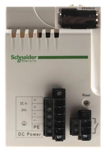 Schneider BMXCPS2010 PLC Power Supply Modicon M340
 -
 Mitsubishi A171SCPU Motion Servo CPU Specifications
 -
 PLC Board with Finder 44.52 Relay Module 6A 250V
 -
 Honeywell DOP 09436601 Measurex Module Data
 -
 Fanuc A20B-8101-0320 CNC Circuit Board
 -
 KUAX 680I V.24 PLC Module 68142304
 -
 Allen Bradley 1785-L30B PLC 5/30 Processor
 -
 Phoenix ILC 191 ETH 2TX 2700976 Ethernet Controller
 -
 Siemens 6SY7000-0AC80 PLC Power Supply Module
 -
 Reliance Electric MACS 804.46.20 CWW PLC Drive
 -
 Omron CP1E-N60DR-D PLC CPU 36 Input 24 Output
 -
 Mitsubishi Melsec PLC System A2ACPU A63P AY13E AX82
 -
 Square D PAF361600DC1680 2000A Circuit Breaker
 -
 MERLIN GERIN STR 58U 5000A Electronic Trip Unit
 -
 Omron CJ1W-SCU21-V1 Serial Communication Unit
 -
 SICK S30A-6011EA S3000 Safety Laser Scanner
 -
 Mitsubishi Q00JCPU-S8 Universal Programmable Controller
 -
 Allen-Bradley 20AB9P6C3AYNANC0 PowerFlex 70 AC Drive
 -
 SYSMELEC Handheld Robot Automation Controller
 -
 LG Display LB315WRM-SVA1 32 Inch 4K LCD Panel
 -
 Mitsubishi Kakoki E Series PLC I/O Modules
 -
 Allen-Bradley 1440-VST02-01RA Dynamic Measurement Module
 -
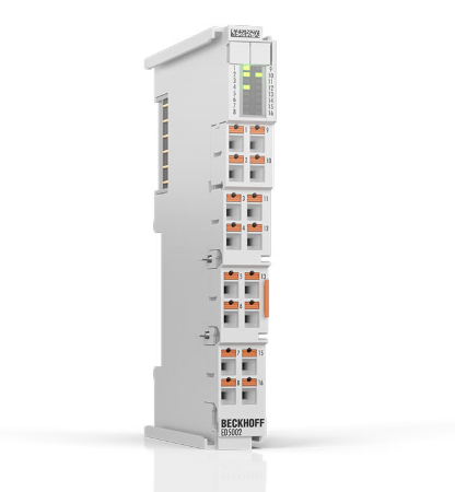 Beckhoff EL5042 EtherCAT Encoder Terminal
 -
 Beckhoff CX5010-0112 Embedded PC Controller
 -
 Guardmaster 440R-D22R2 Safety Relay Specifications
 -
 NL12880BC20-10ND Industrial Display Panel Data
 -
 LFI 12X5326-S1 Slide-in Control Board Technical Data
 -
 Modicon AS-9370-001 Programmable Controller Data
 -
 Mitsubishi Kakoki E-01B-4130 PLC Module Overview
 -
 Guardmaster 440R-D22S2 Dual Input Safety Relay Data
 -
 NL10276AC30-48D Industrial LCD Display Panel Data
 -
 GE ICMFA000000-ABAC Field Control Module Specification
 -
 Siemens 6SN1123-1AB00-0BA1 SIMODRIVE Module Review
 -
 Siemens 6SL3210-1SE23-2AA0 Power Module Technical Data
 -
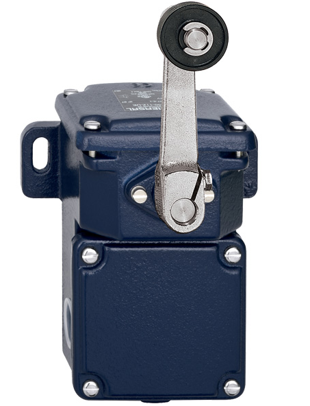 Schmersal T.250-11z-t Limit Switch
 -
 Schmersal T.250-11z-t Limit Switch
 -
 Honeywell 900H32-0102 ControlEdge 900 PLC
 -
 Siemens 6FX1132-1BA01 PCB B84141-A-A40
 -
 BEMAC UST-202-D 1307D PLC Circuit Board
 -
 Mitsubishi HS-MF23-S2A Servo Motor
 -
 B&R 3AI775.6 Analog Input Module
 -
 Omnipure 69003 Rev 11 3-Phase Gate Board PCB
 -
 Pilz 751134 PNOZ s4 C Safety Relay
 -
 Proface PFXGM4301TAD HMI Graphic Panel
 -
 Keyence KV-RC8BXR Programmable Controller
 -
 Siemens 6GK7243-1BX30-0XE0 CP 1243-1 Ethernet Module
 -
 Mitsubishi GT2310-VTBA GT2310-VTBD HMI 10.4 Inch
 -
 Schmersal SRB-NA-R-C.21-24V Safety Relay Module
 -
 Emotron 01-2520-40 M20 Shaft Power Monitor 3x380-500V
 -
 Omron CQM1 SYSMAC PLC System PA203 ID211 OC221
 -
 ABB CI830 3BSE013252R1 Profibus DP V1 Module
 -
 B&R 4PP035.0300-01 Power Panel PLC Module
 -
 SICK S30A-6111CL S3000 PROFINET Safety Laser Scanner
 -
 Siemens 6ES7215-1HG40-0XB0 CPU 1215C AC/DC/RLY
 -
 Automation Direct H2-ECOM100 Ethernet Module Details
 -
 Siemens 6GK1143-0TB01 CP 1430 TF Module Review
 -
 Siemens Simatic 505 10 Slot PLC Rack Technical Review
 -
 Automation Direct EZ-SP Message Display Unit
 -
 Mitsubishi A1SJ71QE71N-B5T Ethernet Interface Unit
 -
 Modicon AS-P810-000 Modbus Plus Processor Unit
 -
 Honeywell 51309241-175 TK-PPD011 PWA Specifications
 -
 Omron S8AS-24006N Smart Power Supply Specifications
 -
 Beckhoff EL3218-0018 EtherCAT Terminal Specifications
 -
 Omron CJ1W-PRT21 PROFIBUS-DP Interface Unit
 -
 Inovance AC810-0122-U0R0 PLC Controller
 -
 Cypress CY7C1021CV33-10ZXCT 1Mb SRAM IC
 -
 GE Fanuc IC695CPU315-CD PLC CPU Module RX3i
 -
 Drager 8312088 PCB Safety Module PAC 5500
 -
 Weltronic H70-T02A S430-V1.2 Weld Timer PLC
 -
 B&R 3AM051.6 PLC Analog Input Module
 -
 Schneider BMENOC0301 Communication Module M580
 -
 Mitsubishi FX3UC-32MT-LT PLC Controller
 -
 Omron TZ-1G TZ-1GV TZ-1GV2 TZ-1GV22 Motion Switch
 -
 Mitsubishi AJ71C21-B1-S2 PLC Controller 424749
 -
 Beckhoff EL5042 EtherCAT Encoder Terminal BiSS C
 -
 Eaton easyE4 Programmable Relay 12 Inputs 8 Outputs
 -
 Carel PCO5 P+ 500BAA000L0 Programmable Controller
 -
 Siemens 6ES7223-1PL22-0XA0 EM223 I/O Module 16DI 16DO
 -
 Lenze EMF2179IB DeviceNet Communication Module
 -
 Mitsubishi Q173DCPU Motion CPU Module
 -
 B&R X20AT2222 Temperature Input Module Pt100
 -
 Siemens SITOP UPS1100 Battery Module 7Ah 6EP4134-0GB00-0AY0
 -
 Mitsubishi QJ71DN91 DeviceNet Master Slave Module
 -
B&R X20AO4622 Analog Output Module 4 Channels
-
 B&R X20CP1486 Controller Manual
 -
 Siemens 6ES7134-4GB51-0AB0 Module Manual
 -
 Schneider LMC201CAA10000 Controller Manual
 -
 Fuji Electric NP1L-RS4 Module Guide
 -
 Mitsubishi FX2N-16LNK-M Master Guide
 -
 Yaskawa SGDM-08ADA SGMAH-08AAA41 Manual
 -
 Fanuc A20B-0008-0470 Board Manual
 -
 Calpeda T 70/B Module Specifications
 -
 Eurotherm TC3000 Power Drive Specifications
 -
 Mitsubishi QJ71GP21S-SX Module Manual
 -
 B&R X20AI4622 Analog Input Module 4 Channels
 -
 Siemens Simatic S5 PLC I/O and CPU Modules
 -
 Tel 38950 PCB Board 5044-000171-11 AP9Z-2033A
 -
 Sanyo PLC-XTC50L Multimedia Projector
 -
 Siemens 6GK7243-5DX30-0XE0 CP 243-5 AS-Interface
 -
 Omron V680-CA5D02-V2 RFID Controller
 -
 Pilz 570640 PSEN SL-1.0P Safety Switch
 -
 Schneider LXM62DD27D21000 Servo Drive
 -
 Pilz 401112 PITswitch en1.1a-5m-s Emergency Stop Switch
 -
 Pilz 774350 P2HZ X3 Safety Relay
 -
 Siemens S30810-Q1113-X4-6/02 EWSD Module Board
 -
 Honeywell 30751044-008 ROM PLC Control Board
 -
 Allen-Bradley 440R-W23219 MSR310P Safety Relay
 -
 Siemens 6GK5204-2BB10-2AA3 Industrial Ethernet Switch
 -
 Siemens YSU C32353ADDAGS C98043 PC Board
 -
 Schneider TM241CEC24T PLC Controller Modicon M241
 -
 VARIAN E15000591 PLC PCB Assembly 132102
 -
 Schneider Electric HMIG3U PLC Controller Module


