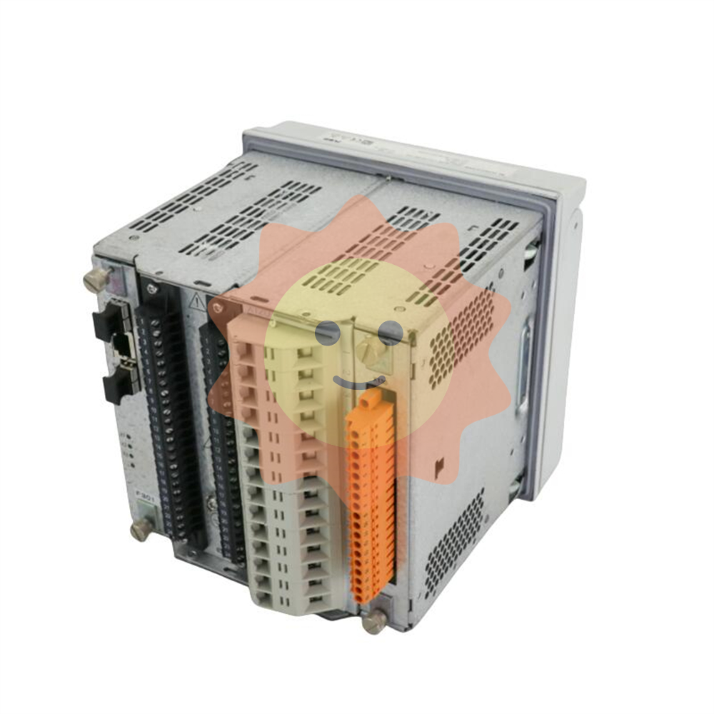
ABB B5EC HENF105077R1 is an economical electronic motor protection relay based on microprocessor architecture, designed for small and medium-sized AC motors in the industrial field. Its core function is to monitor the motor's operating status in real time, provide fast and reliable protection against common faults such as overload, phase loss, and current imbalance, and avoid serious consequences such as motor winding burnout and mechanical structure damage caused by fault expansion. This product belongs to ABB's motor control and protection product line, integrating streamlined and practical protection algorithms with industrial grade hardware design. It has the characteristics of high cost-effectiveness, simple configuration, and strong anti-interference. It is widely used in the protection scenarios of general motors such as water pumps, fans, conveyors, compressors, covering multiple industries such as water treatment, building HVAC, light industry manufacturing, and agricultural irrigation.
ABB B5EC HENF105077R1 Electronic Motor Protection Relay
Product Overview
ABB B5EC HENF105077R1 is an economical electronic motor protection relay based on microprocessor architecture, designed for small and medium-sized AC motors in the industrial field. Its core function is to monitor the motor's operating status in real time, provide fast and reliable protection against common faults such as overload, phase loss, and current imbalance, and avoid serious consequences such as motor winding burnout and mechanical structure damage caused by fault expansion. This product belongs to ABB's motor control and protection product line, integrating streamlined and practical protection algorithms with industrial grade hardware design. It has the characteristics of high cost-effectiveness, simple configuration, and strong anti-interference. It is widely used in the protection scenarios of general motors such as water pumps, fans, conveyors, compressors, covering multiple industries such as water treatment, building HVAC, light industry manufacturing, and agricultural irrigation.
As the core safety component of the motor control circuit, B5EC relay can be directly connected to the motor main circuit and control circuit without complex external circuit assistance, achieving closed-loop control of "monitoring judgment protection". Its standardized installation size and universal communication interface enable it to flexibly adapt to various low-voltage distribution cabinets and automation control systems. It is suitable for motor protection configuration in new projects and also facilitates the upgrading and replacement of old motor protection equipment, providing users with an economical and efficient motor safety guarantee solution.
Core functional characteristics
Accurate and practical fault protection function
The B5EC relay focuses on the core risk points of motor operation and is equipped with a series of targeted protection functions: firstly, overload protection, which adopts inverse time protection characteristics and can automatically match the protection curve according to the rated current of the motor (adjustable from 0.5A-50A). When the motor experiences mild overload, the action time is extended to avoid false protection. When the overload continues, the power supply is quickly cut off, and the protection curve complies with IEC 60947-4-1 standard; The second is phase loss protection, which monitors the three-phase current of the motor in real time. When a phase current is detected to be zero or the three-phase current difference exceeds 30%, the protection action is triggered within 2 seconds, effectively preventing local overheating of the motor caused by phase loss operation; The third is current imbalance protection, which can set the imbalance threshold through a dip switch (15%/30% selectable), suitable for motors with different load characteristics.
In addition, the relay also has a stall protection function. If a stall fault occurs during motor start-up or operation, the current will sharply rise to 6-10 times the rated value. The relay can trigger the protection within 500ms after detecting the abnormality; Simultaneously supporting PTC temperature protection input, it can be connected to the built-in PTC thermistor of the motor to directly monitor the winding temperature. When the temperature exceeds the threshold, the power supply is cut off, forming a dual protection of "current+temperature".
Simple and intuitive parameter configuration and status monitoring
To improve the convenience of on-site use, B5EC relay adopts a simplified configuration method of "dip switch+indicator light", which can complete core parameter settings without connecting to a computer. Users can directly set key parameters such as the rated current of the motor (adjustable in stages, with an accuracy of 0.1A), enable/disable protection functions (such as whether PTC protection is enabled), and action delay time (adjustable from 0.1s-10s) through the 8-bit dip switch on the panel. The configuration process does not require professional programming knowledge and can be completed by ordinary electricians.
In terms of status monitoring, the relay panel is equipped with 6 LED indicator lights, corresponding to power, operation, overload alarm, phase loss alarm, locked rotor alarm, PTC alarm and other statuses. The operation and maintenance personnel can intuitively judge the motor operation status and fault type through the color of the indicator lights (green constant light is normal, red flashing is alarm). At the same time, the relay has a fault memory function, which can lock the most recent fault type until manually reset, making it easy to trace and troubleshoot the cause of the fault.
Industrial grade reliability and environmental adaptability
In response to the complex operating environment of industrial sites, B5EC relays have adopted multiple reliability assurance measures in hardware design: internal photoelectric isolation technology is used to electrically isolate the current acquisition circuit from the control output circuit, with an isolation voltage of ≥ 2000V AC, effectively preventing external interference signals from entering and high-voltage counterattacks; Through the IEC 61000-4 series basic electromagnetic compatibility testing, it has the ability to discharge static electricity at ± 4kV contact and withstand surges at ± 1kV power supply terminals, and can work stably near equipment such as frequency converters and contactors.
The relay adopts ABS flame-retardant shell, with a protection level of IP40. The working temperature range covers -10 ℃~+60 ℃, and the humidity adaptation range is 5%~95% (no condensation). It can withstand harsh conditions such as workshop dust, humidity, and slight vibration; The output contacts are made of silver tin oxide material and have the on-off capability of 5A/250V AC. The mechanical life is up to 1 million times and the electrical life is up to 100000 times, ensuring the reliable execution of protection commands.
Flexible Installation and System Adaptation Capability
The B5EC relay adopts two installation methods: standard DIN 35mm rail installation and panel embedded installation. The installation size is 45mm × 75mm × 110mm (width × height × depth), which can flexibly adapt to various low-voltage distribution cabinets and control boxes, saving installation space. Its input power supports AC 220V/380V dual voltage adaptive, without manual switching, and can be directly connected to motor control circuits of different voltage levels, reducing the difficulty of selection and installation.
In terms of system adaptation, the relay is equipped with one set of normally open and one set of normally closed output contacts, which can be directly connected to the contactor coil of the motor control circuit to achieve automatic shutdown in case of faults; At the same time, it supports docking with control systems such as PLC and HMI, and uploads fault signals through output contacts to achieve multi device collaborative control and centralized monitoring, meeting the integration requirements of automated production lines.
Key technical parameters
parameter category
Specific parameters
Instructions
Applicable motor types
Three phase asynchronous motor
Suitable for small and medium-sized motors ranging from 0.37kW to 22kW
Current protection range
0.5A-50A (direct access)
Adjustable in 20 levels, with an accuracy of ± 5%
protection function
Overload, phase loss, current imbalance, locked rotor, PTC temperature protection
Core functions can be independently enabled/disabled
Action response time
Phase loss: ≤ 2s; locked rotor: ≤ 500ms; overload: inverse time limit
Quick response, reducing fault losses
input power
AC 220V/380V ±10%,50/60Hz
Dual voltage adaptive, no need for manual switching
Output contact
1 group normally open+1 group normally closed, capacity 5A/250V AC
Directly control the contactor coil
isolation level
Input and output isolation ≥ 2000V AC
Ensure the safe operation of the system
working environment
Temperature: -10 ℃~+60 ℃; Humidity: 5%~95% (no condensation); Protection level: IP40
Adapt to the conventional industrial site environment
Electromagnetic Compatibility
Compliant with IEC 61000-4-2/3/5 standard
Have basic anti-interference ability
installation dimensions
45mm (width) x 75mm (height) x 110mm (depth)
Support rail and panel installation
weight
About 200g
Lightweight design, easy installation
Installation and configuration points
Installation specifications
-The relay supports DIN 35mm standard rail installation and panel embedded installation. The installation location should be selected in a well ventilated area, away from high temperature heat sources (such as motors and heaters), strong electromagnetic interference sources (such as frequency converters), and areas washed away by rainwater. Outdoor use requires the use of a protective box;
-When installing the guide rail, the distance between the relay and adjacent equipment should not be less than 10mm to ensure good heat dissipation; When installing the panel, the thickness of the panel should be between 1mm-5mm, and the size of the installation hole should match the relay installation ear to avoid loose installation;
-Before wiring, the motor power supply and control circuit power supply must be disconnected, and wiring must be strictly in accordance with the terminal block markings: the current input terminals (A, B, C) are respectively connected to the three-phase wires of the motor main circuit, the power terminals (L, N) are connected to the control circuit power supply, the output contacts (NO, NC, COM) are connected to the contactor coil circuit, and the PTC terminal is connected to the built-in PTC thermistor of the motor;
-The current input wire should use copper wire with a cross-sectional area of ≥ 1.5mm ², and the power and output circuit wires should use copper wire with a cross-sectional area of ≥ 1.0mm ². All wiring terminals must be tightened to avoid measurement errors or protection misoperations caused by poor contact;
-After the wiring is completed, check whether the relay installation is firm, whether the wires are under pressure or pulled, and ensure that there is no risk of short circuit before connecting the power supply.
Configuration Process
1. Parameter confirmation: Based on the information on the motor nameplate, confirm key parameters such as the rated current, rated voltage, and whether there is a built-in PTC thermistor as the basis for relay configuration;
2. Dial configuration: Parameter settings are completed through the dial switch on the relay panel: the first to fourth digits dial to set the rated current of the motor (refer to the current dial correspondence table in the product manual), the fifth to sixth digits set the protection action delay, the seventh digit sets the current imbalance threshold (15%/30%), and the eighth digit sets the PTC protection function enabled/disabled;
3. Function test: Connect the control circuit power supply, and the relay power indicator light will turn on; Manually trigger the motor to simulate a fault (such as disconnecting one phase current), observe whether the corresponding fault indicator light is on, whether the contactor is reliably disconnected, and verify the effectiveness of the protection function;
4. Reset and Operation: After the fault test is completed, reset the fault state through the reset button on the relay panel, connect the main power supply of the motor, start the motor, and observe whether the operation indicator light is lit up normally to ensure that the motor enters normal operation.
Maintenance and troubleshooting
Daily Maintenance
Daily maintenance should follow the principle of "simple inspection and regular verification", including: checking the relay panel indicator lights for normal operation every week, and ensuring that there are no abnormal alarms during motor operation; Clean the dust on the surface of the relay every month, check whether the wiring terminals are loose due to vibration, and focus on checking the current input terminals; Test the effectiveness of protection functions by simulating faults every quarter, such as disconnecting one phase power supply to test phase loss protection, and artificially increasing the load to test overload protection; Check the continuity performance of relay contacts annually, and measure the output contact resistance with a multimeter to ensure good contact.
Common troubleshooting
Fault phenomenon
Possible reasons
troubleshooting method
The power indicator light is not on, and the relay is unresponsive
The power supply is not connected; Abnormal power supply voltage; Loose power wiring
Check if the power switch is closed and measure if the power voltage is within the range of AC 220V/380V ± 10%; Re plug and unplug the power supply wiring, check if the terminals are securely fastened
Incorrect triggering of overload protection during normal operation of the motor
The rated current parameter setting is too small; Excessive motor load; Poor heat dissipation
Check the motor nameplate and readjust the rated current set for the dial code; Check if the motor load exceeds the rated value; Clean the relay and motor cooling channels
When the motor fails, the relay does not operate
The corresponding protection function is not enabled; Current wiring error; Output contact fault
Check the dip switch to confirm that the protection function is enabled; Check if the current input terminal wiring is correct; Measure the on/off status of the output contacts with a multimeter to determine if there is a fault
PTC alarm triggered incorrectly
Loose wiring of PTC thermistor; PTC parameter mismatch; Poor heat dissipation of the motor
Check if the PTC wiring terminals are securely fastened; Confirm that the PTC thermistor specifications match the relay; Check if the motor cooling fan is working properly and clean the dust on the cooling fins
The fault indicator light is on but the motor is not stopped
Output contact wiring error; Contactor malfunction; Output circuit disconnection
Check if the wiring between the output contact (NO/NC/COM) and the contactor coil is correct; Test whether the contactor coil is powered on normally; Check if the output circuit wire is broken

- User name Member Level Quantity Specification Purchase Date
- Satisfaction :
-


