The model identification of DS200DCFBG series cards contains clear product positioning and configuration information. Different suffix models have differences in interface details, and the core functions and adaptation scenarios remain consistent. The specific identification analysis is as follows:
-DS200DCFBG: series core model, "DS200" represents GE General Industrial Control Board platform, "DCFBG" is the abbreviation of "DC Feedback Board", which clarifies the core functional attributes of the board;
GE DS200DCFBG2BNC DS200DCFBG1BNC DC Feedback Board
Board core identification and basic information
The model identification of DS200DCFBG series cards contains clear product positioning and configuration information. Different suffix models have differences in interface details, and the core functions and adaptation scenarios remain consistent. The specific identification analysis is as follows:
-DS200DCFBG: series core model, "DS200" represents GE General Industrial Control Board platform, "DCFBG" is the abbreviation of "DC Feedback Board", which clarifies the core functional attributes of the board;
-DS200DCFBG1BNC/DS200DCFBG2BNC: Specific model differentiation, suffix "1" and "2" represent the difference in the number of BNC interfaces (1 and 2 core feedback interfaces respectively), "BNC" indicates the interface type as BNC coaxial interface, compatible with standard coaxial cables, ensuring the stability of high-frequency feedback signal transmission;
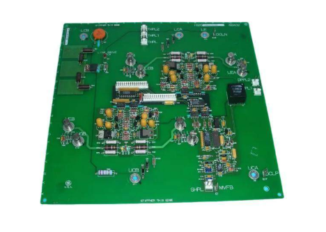
The board adopts a standard industrial grade PCB design, with dimensions suitable for GE universal control system chassis (such as Mark V, Mark VIe series). The installation method is snap on+screw fixation, which has good mechanical stability and can effectively resist vibration interference in industrial sites. The front of the board integrates interface terminals, status indicator lights, and adjustment knobs for easy on-site installation, debugging, and status observation.
Key technical parameters
The technical parameters of the GE DS200DCFBG series DC feedback board are designed around signal acquisition accuracy, interface performance, and environmental adaptability. The core parameters are as follows:
1. Core feedback signal specifications:
Signal type: DC voltage/current feedback signal, supporting input of tachometer generator (TG) signal, resolver signal, and Hall sensor signal;
2. Input range: Voltage signal 0-10V DC, 0-5V DC, current signal 4-20mA DC, speed measurement signal supports up to 10kHz pulse frequency;
3. Collection accuracy: Voltage signal collection error is ≤± 0.1% FS, current signal collection error is ≤± 0.2% FS, ensuring the accuracy of feedback signals;
4. Interface configuration: DS200DCFBG1BNC includes 1 BNC main feedback interface and 2 terminal type auxiliary interfaces; DS200DCFBG2BNC includes 2 BNC main feedback interfaces and 2 terminal type auxiliary interfaces. The BNC interface has a characteristic impedance of 75 Ω and is compatible with standard coaxial cables such as RG58.
5. Signal processing and output:
Conditioning circuit: Integrated high-precision instrument amplifier and low-pass filter, which can effectively suppress 50Hz/60Hz power frequency interference and high-frequency noise;
6. Output signal: Standard 0-5V DC conditioned signal, compatible with GE Mark series controllers, output impedance ≤ 100 Ω;
7. Response time: Signal conditioning delay ≤ 10 μ s, meeting the control requirements of real-time speed regulation system.
8. Power supply and power consumption:
Input voltage: ± 15V DC (± 5%),+5V DC (± 3%) dual power supply;
9. Typical power consumption: ≤ 0.3A at ± 15V, ≤ 0.5A at+5V, rated power consumption ≤ 5W, low energy consumption and stable heating.
10. Fault monitoring and protection:
Monitoring function: supports input signal loss, overvoltage, overcurrent fault monitoring, and has fault signal locking function;
11. Protection output: 1 fault relay dry contact output (capacity: 2A/250V AC), which can directly trigger system alarm or shutdown protection.
12. Environmental adaptability: The working temperature range is 0 ℃~+60 ℃, the storage temperature range is -40 ℃~+85 ℃, the relative humidity is 5%~95% (no condensation), and the anti electromagnetic interference level meets the IEC 61000-4-4 (Electric Fast Transient Pulse Group) Level 3 standard.
Functional features and advantages
1. High precision signal acquisition capability: Using a 16 bit ADC chip and a high-precision reference voltage source, combined with differential input design, effectively improves signal acquisition accuracy and common mode rejection ratio (CMRR ≥) 80dB@50Hz )It can accurately capture subtle changes in key parameters such as motor speed and armature current;
2. Flexible signal adaptability: Supports multiple types of feedback sensor signal inputs, and can quickly configure signal types, input ranges, and filtering parameters through the dip switch on the board. It can adapt to different models of DC motor speed control systems without replacing hardware, reducing system integration costs;
3. Reliable fault protection mechanism: It has multi-level fault monitoring function. When a signal abnormality is detected, the fault output can be triggered within 10ms. At the same time, the fault type (signal loss/overvoltage/overcurrent) is clearly indicated through LED indicator lights, which facilitates on-site engineers to quickly locate the problem and improve system operation and maintenance efficiency;
4. Strong environmental adaptability design: The PCB board is treated with moisture-proof and corrosion-resistant coatings, and key components are selected from industrial grade wide temperature products. The power input end is equipped with an EMC filter circuit, which can work stably in industrial sites with high dust and humidity, extending the service life of the board;
5. Good system compatibility: Designed specifically for mainstream control systems such as GE Mark V and Mark VIe, the interface signal and controller are perfectly matched, supporting hot plugging (which needs to be operated in the system shutdown state), and there is no need to reconfigure system parameters when replacing boards, improving maintenance convenience.
Typical application scenarios
The DS200DCFBG series DC feedback board, as the core component of DC speed regulation systems, has achieved mature applications in multiple industrial fields, with main scenarios including:
-Metallurgical industry rolling mill speed regulation: In the DC rolling mill speed regulation system of steel plate cold rolling and hot rolling production lines, the speed of the rolling mill motor and the feedback signal of the armature current are collected to provide accurate data for the controller, ensuring the stability of the rolling mill speed and improving the precision of steel plate rolling;
-Mining equipment drive control: applied to the DC drive system of mining elevators and belt conveyors, real-time monitoring of motor operation status. When overload, abnormal speed and other situations occur, the protection mechanism is quickly triggered to ensure the safe operation of mining equipment;
-Paper machine control in the papermaking industry: In the DC motor speed control system of the net and press parts of the paper machine, multiple motors are synchronized through precise feedback signals to ensure uniform paper thickness and improve the quality of papermaking products;
-Chemical industry mixing equipment: used as a speed control system for chemical reaction kettle mixing motors, collecting motor speed feedback signals, and cooperating with controllers to achieve precise adjustment of mixing speed, meeting the process requirements of different chemical reactions;
-Universal industrial DC speed regulation: Suitable for various types of universal DC motor drive systems, such as machine tool spindle drive, conveyor equipment drive, etc., providing core feedback support for the smooth operation and precise speed regulation of motors.
Precautions for use
Before installing the board, it is necessary to confirm the control system model and power supply voltage to ensure compatibility with the DS200DCFBG series board. It is strictly prohibited to power on the board when the voltage does not match;
When connecting BNC interfaces, it is necessary to ensure that the plug and socket are tightly fitted to avoid signal attenuation or interference caused by poor contact. Before connecting, the dust and oxide layer at the interface should be cleaned;
When wiring the signal, the feedback signal line should be laid separately from the power cable (with a spacing of ≥ 30cm). It is recommended to use shielded coaxial cable for the feedback signal line, and the shielding layer should be grounded at one end to reduce electromagnetic interference;
4. The configuration of the board parameters (signal type, range, etc.) should match the sensor output parameters. After the configuration is completed, signal calibration should be performed to ensure feedback accuracy;
5. During the operation of the system, it is necessary to regularly check the status indicator lights of the board. When the fault light is on, it is necessary to stop the machine in a timely manner for troubleshooting to avoid the expansion of the fault;
6. When maintaining the board, the power supply of the control system should be cut off first. It is strictly prohibited to plug and unplug the board with power on. When replacing the board, attention should be paid to electrostatic protection to avoid static electricity damaging electronic components.
- User name Member Level Quantity Specification Purchase Date
- Satisfaction :
-


