GE DS200TCDAG1A Digital I/O Board
GE DS200TCDAG1A Digital I/O Board
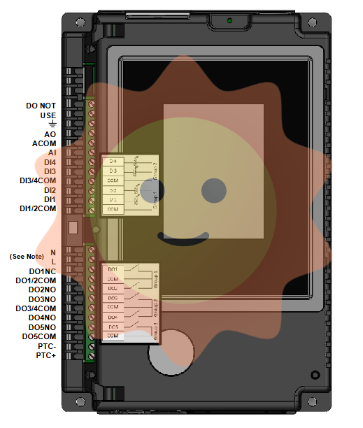
Part Number DS200TCDAG1A Manufacturer General Electric Country of Manufacture As Per GE Manufacturing Policy Series Mark V Function Module Availability In StockDS200TCDAG1A is a Digital I/O Board manufactured and designed by General Electric as part of the Mark V LM Series used in gas turbine control systems. The Digital IO Board (TCDA), is situated in the Q11, Q51, and Q21 digital I/O cores if any are present. The two TCRA boards' contact output (relay/solenoid) signals are processed by TCDA along with digital contact input signals from the DTBA and DTBB terminal boards.
The TCQC board in R1, the CTBA terminal board in R5, and R2 if Q21 is installed all receive the signals via the IONET. A serial communication network called the IO Network (IONET) links an IO Engine with any potential TCDA board. The TCDA boards in the digital cores (Q11, Q21, or Q51), in P1 all exchange data. The physical IONET connections, however, are made to the CTBA in R5 or the TCQC board in R1 and R2. The network only transmits data that is address-specific. Data is therefore routed to either the TCDA TCDA CONNECTORS: JP - Distributes power from the TCPS board to the Q11, Q21, and Q51 cores, respectively, in the R1, R2, and R5 cores. JQ - Connects to the DTBA board's JQR socket. transports the DTBA board's contact input signals to the TCDA board. JR - Attaches to the DTBB board's JRR socket. is responsible for transporting the contact input signals from the DTBB board to the TCDA board. JO1 - writes the relay/solenoid contact output signals to location 4 of the TCRA board.
Not utilized in Q11 since TCQE in R1 directly controls the relays at location 4. JO2 - writes the relay/solenoid contact output signals to location 5 of the TCRA board. TCDA CONFIGURATION: HARDWARE: The TCDA board has eight physical jumpers. For factory testing, use J1 and J8. Resistor IONET termination is for J2 and J3. The board's IONET ID is configured using J4, J5, and J6. Stall timer enable is J7. The hardware jumper settings for this board are described in Appendix A and on the operator interface's hardware jumper screen. SOFTWARE: The I/O Configuration Editor on the HMI is where the I/O configuration constants for the contact input inversions are entered. TCDA CONTACT INPUT CIRCUITS: Through the JR and JQ connectors, the TCDA board receives contact inputs from the DTBA and DTBB terminal boards. The TCDA board's circuitry processes the signals, times any state changes, and sends the signals to the IONET through the JX1 (JX2) connector. Software is used to invert the contact signals using I/O configuration variables.
Compatibility
ƒ Compatible with any Series 90-30 CPU except IC693CPU321 and IC693CPU340. Configuration size is limited for CPU311/313/331, as described on the next page.
ƒ Requires release 8.0 CPU firmware. The latest Release 10 is recommended, if available for the particular CPU.
ƒ Requires CIMPLICITY Machine Edition Logic Developer PLC version 3.0 plus the appropriate service pack or special (or a version later than 3.0).
ƒ Not compatible with the VersaPro™, Control, or Logicmaster™ programming software.
ƒ The Series 90-30 Hand-Held Programmer (IC693PRG300) cannot be used to configure this module. New Features The Series 90-30 DeviceNet Master Module allows a Series 90-30 PLC to send and receive I/O data from a DeviceNet network.
Module features include:
ƒ Support for all standard data rates (125K, 250K, 500K)
ƒ Support for 255 bytes input data transfer and 255 bytes output data transfer per slave
ƒ Support for 3972 bytes of input data transfer and 3972 bytes of output data transfer per master
ƒ Support for two I/O connections per Slave - Typically one connection is used for Polled and the other is used for Strobe, Cyclic, or COS
ƒ Support for Poll, Strobe, Cyclic and COS I/O Connections, Fragmented I/O and Explicit Messaging
ƒ Support for Unconnected Message Manager (UCMM) with 1 proxy connection per slave device
ƒ Support for configuration of the global scan rate
ƒ Support for configuration of update rates for Poll and COS/Cyclic on a connection basis
ƒ Support for PLC-application initiated explicit messaging via a COMMREQ
ƒ Master can be configured to operate as a slave simultaneously with master operation
ƒ Configurable fault behavior on loss of communication
ƒ Reports loss or reestablishment of communication with slaves in PLC fault table (configurable)
ƒ Support for 64 network device status bits (note: the bit for the master itself is always zero)
ƒ Firmware update via service port on module

- User name Member Level Quantity Specification Purchase Date
- Satisfaction :
-


