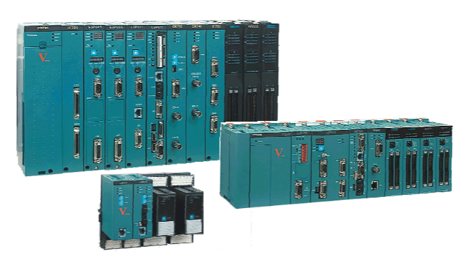
GE IS215VCMIH1C 3 Network Version for TMR Systems
GE IS215VCMIH1C 3 Network Version for TMR Systems
Part Number IS215VCMIH1C Manufacturer General Electric Country of Manufacture As Per GE Manufacturing Policy Series Mark VI Function Module Availability In StockIS215VCMIH1C is a Bus Master Controller Board manufactured and designed by General Electric as part of the Mark VIe Series used in distributed control systems. A VCMI board in the VME rack enables two-way communication between the I/O processor boards and the controller. Other system elements, like an operator interface or PLC, are communicated using the controller's Ethernet port. The controller Genius port can be used to connect additional PLC I/O to the system. The system employs a low voltage variant of the common VME rack power supply and is powered by 24 V dc.
The signal conditioning on DIN-type terminal boards is always the same as on T-type terminal boards, and the mentioned I/O specifications are applicable. However, the boards do not support TMR, and there are differences in the number of inputs and outputs as well as the grounding rules. Space is conserved by using high-density Euro-Block terminal blocks that are permanently mounted. The terminals on the blocks can accommodate up to two #14 wires or one #12 wire. The most common wire size is #18 AWG. IS215VCMIH1C Operation The controller has software that is specifically designed for use with steam, gas, land-marine derivative (LM), or balance of plant (BOP), goods. Assuming a normal collection of blocks of average size, it can execute up to 100,000 rungs or blocks every second.
The controller is able to synchronize to the VCMI board's clock within 100 microseconds thanks to an external clock interrupt. The VCMI board uses the VME bus to send and receive external data to and from the control system database (CSDB) in the controller. The process inputs and outputs from the I/O boards make up the data in a simplex system. The inputs from the input boards, singular inputs from simplex boards, computed outputs to be voted by the output hardware, and the internal state values that need to be exchanged between the controllers make up the data in a TMR system.
IS215VCMIH1C Installation The controller and a VCMI are the two components that make up a control module. Three different types of racks are available, including the GE Fanuc integrator's rack displayed in the accompanying figure and the two Mark VI rack sizes displayed in the section titled "VCMI - Bus Master Controller." Only standalone modules with remote I/O are used in the shorter GE Fanuc rack. Longer Mark VI racks that support both local and remote I/O are available. A cooling fan is positioned above or below the controller depending on which rack is being utilized. A VDSK board is also necessary for the stand-alone control module used with a GE Fanuc integrator's rack in order to provide fan power and identify the rack through an ID connection. Diagnostics Internal power supply buses of 5 V, 12 V, 15 V, and 28 V are monitored and alerted.
The alarm settings are customizable and are typically set at 3.5%, with the exception of the 28 V supplies, which are set to 5.5%. Diagnostic signals from the power distribution module (PDM) are also monitored through J301. Ground fault and over/under voltage detection on the P125 V bus, two differential 5V dc analog inputs, P28A and PCOM for external monitor circuits, and digital inputs are among them.
Instructions and warnings related to the operation of the product:
The following specifications must be strictly observed:
The technical specifications and typical applications of the product system must be strictly observed.
PERSONNEL TRAINING: Only trained personnel may install, operate, maintain or repair the product system. These personnel must be instructed on the
Hazardous area conditions must be instructed and explained to these personnel.
Unauthorised modifications: No modifications or structural changes may be made to the product system.
Maintenance Responsibility: It must be ensured that the product system is only used under appropriate conditions and in a condition that is fully fit for purpose.
Working environment: The user must fulfil the specified environmental conditions:
Safety regulations
The following safety regulations must be fully observed when (maintenance) work is carried out on the product system:
1 Disconnect completely.
2 Secure to prevent reconnection.
3 Confirm that the installation has been completed.
4 Perform grounding and short-circuiting.

- User name Member Level Quantity Specification Purchase Date
- Satisfaction :
-


