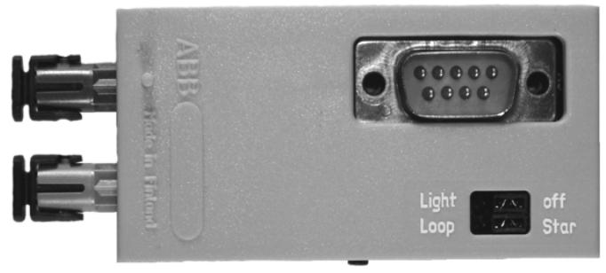
The ABB RER 103 bus connection module is used for connecting RE_500 equipment with optical fiber SPA and LON ® The interface unit between the IEC 60870-5-103 bus can convert fiber optic signals and RS-485 electrical signals bidirectionally, and plug them into the RE_500 equipment backplane through a 9-pin D-type connector to obtain power (5V DC) from it; Supports two bus topologies: Loop and Star. The topology and line idle state (light on/off) are selected through jumpers and correspond to different protocols (SPA only has Loop+light off), LON ® Only star shaped+light off, IEC 103 supports star shaped+light on/off); We provide two types of connector combinations (4 models): plastic fiber and glass fiber. The maximum transmission distance for glass fiber is 1000m, and for plastic fiber it is 10m. The maximum data transmission rate is 1.25 Mbps, and the working temperature range is -10... 55 ° C.
ABB RER 103 bus connection module
Product Overview
The ABB RER 103 bus connection module is used for connecting RE_500 equipment with optical fiber SPA and LON ® The interface unit between the IEC 60870-5-103 bus can convert fiber optic signals and RS-485 electrical signals bidirectionally, and plug them into the RE_500 equipment backplane through a 9-pin D-type connector to obtain power (5V DC) from it; Supports two bus topologies: Loop and Star. The topology and line idle state (light on/off) are selected through jumpers and correspond to different protocols (SPA only has Loop+light off), LON ® Only star shaped+light off, IEC 103 supports star shaped+light on/off); We provide two types of connector combinations (4 models): plastic fiber and glass fiber. The maximum transmission distance for glass fiber is 1000m, and for plastic fiber it is 10m. The maximum data transmission rate is 1.25 Mbps, and the working temperature range is -10... 55 ° C.
Product General Information
Core function: As a RE_500 device and fiber optic bus (SPA, LON) ®、 The interface unit of IEC 60870-5-103 realizes bidirectional signal conversion - converting the optical signal of the fiber optic bus into the RS-485 electrical signal required by RE_500 equipment, and vice versa.
Physical connection:
Insertion method: Install through the 9-pin D-type micro connector (RS-485 interface) on the RE_500 device backplane
Scope of application: Compatible with all RE_500 devices equipped with 9-pin D-type connectors
Power supply and special design:
Power source: Take power from the D-type connector of RE_500 device (5V DC)
Special components: including LON ® Node Service Pin, connected to the Neuron of the connected device via RS-485 interface ® chip
Principle of operation
Topology and State Selection:
Supported topologies: Loop, Star, set through jumper wires
Line idle state: You can choose "Light on" or "Light off" and set it through jumper wires
Signal transmission rules:
Ring topology: messages received from fiber optic receivers are simultaneously transmitted to fiber optic transmitters and RS-485 interfaces
Star topology: Messages received from fiber optic receivers are only transmitted to the RS-485 interface
Common rule: Messages received from the RS-485 interface are transmitted to the fiber optic transmitter in both topologies
Corresponding relationship between protocol and topology/state (Table 2-1):
Topology: Line Idle State (Light on/off) Supports Protocol
Star Off LON ®、 IEC 60870-5-103
Star on IEC 60870-5-103
Loop Off SPA
Loop On Not supported
Special feature: in LON ® In bus communication, RER 103 supports collision detection
Structural Design (Construction)
Hardware composition: consisting of a printed circuit board and a plastic case
Fiber optic connection:
Input interface: Rx (receiving external fiber optic signals)
Output interface: Tx (sending fiber optic signals externally)
Fiber processing requirements: Follow manual 1 MRS752089-MUM《Plastic-core fibre-optic cables. Features and instructions for mounting》 Installation specifications
Connector type: Two fiber optic connector combination options are available:
Dual plastic fiber optic connector
Double glass fiber optic connector
1 plastic+1 glass fiber optic connector
Mechanical dimensions (Figure 3-1):
Width: 35.0mm
Height: 73.0mm
Depth: 20.0mm
Type designation
Model classification rules: Divided by the fiber type (plastic/glass) of the transmitter and receiver, there are a total of 4 models (Table 4-1):
Type designation, transmitter type, receiver type, ordering number
RER 103 Plastic RER103-BB Plastic
RER 103 Plastic Glass RER103-BM
RER 103 Glass Plastic RER103-MB
RER 103 Glass RER103-mM
Compatibility limitations:
LON ® Star coupler (RER 111)
IEC star coupler (125)
The above two types of couplers only support transceiver connections of glass glass and plastic plastic, and do not support mixed types (plastic glass, glass plastic)
Fiber optic connectors and technical data
Fiber optic connector parameters (Table 5-1):
Parameter type: Glass fiber, Plastic fiber
Cable connector ST connector Snap in connector
Cable diameter 62.5/125 μ m 1 mm
Maximum cable length 1000 m 10 m
Wavelength 820-900 nm 660 nm
Transmission power -13 dBm (model HFBR-1414) -13 dBm (model HFBR-1521)
General Technical Parameters (Table 5-2):
Auxiliary power supply: provided by the host device (5V DC)
Maximum power consumption (Burden):~0.4 W
Max data transfer rate: 1.25 Mbps
Operating temperature range: -10... 55 ° C
Storage temperature range: -40... 70 ° C
- User name Member Level Quantity Specification Purchase Date
- Satisfaction :
-


