
Tektronix AWG70000 series arbitrary waveform generator
Compliance certification: Complies with EN 61010-1, UL 61010-1, CSA C22.2 No. 1010.1 safety standards to ensure compliance in industrial use.
Tektronix AWG70000 series arbitrary waveform generator
Product Overview
Product coverage: AWG70000 series full models (such as AWG70001 single channel, AWG70002 dual channel), supporting software version 7.0 and above.
Compliance certification: Complies with EN 61010-1, UL 61010-1, CSA C22.2 No. 1010.1 safety standards to ensure compliance in industrial use.
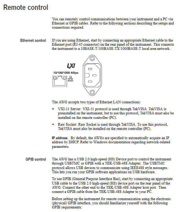
Remote control setup: Ethernet and GPIB
1. Ethernet control (recommended)
(1) Hardware connection
Connect the Ethernet port of the instrument Rear panel to the LAN switch/PC using an RJ-45 Ethernet cable, supporting speeds of 10BASE-T (10Mbps), 100BASE-TX (100Mbps), and 1000BASE-T (1Gbps).
(2) Protocol and Configuration
Protocol type requirements for application scenarios
VXI-11 Server instrument and PC are both equipped with TekVISA standard remote control, with strong compatibility
Both the Raw Socket instrument and PC are equipped with TekVISA high-speed data transmission and low latency
DHCP is enabled by default for IP acquisition, and the IP is automatically obtained from the router. If a fixed IP is required, the laboratory's fixed network environment can be modified through Windows network settings
2. GPIB control (compatible with traditional devices)
(1) Hardware connection
Instrument Rear panel USB 2.0 HS Device port → connect to the host port of TEK-USB-488 adapter;
Connect the GPIB port of the adapter to the GPIB card/interface of the PC using a GPIB cable.
(2) Key configuration rules
Address uniqueness: Each device on the bus must be assigned a unique address (1-30), which cannot be duplicated;
Bus limitation: Up to 15 devices can be connected, with 1 device required every 2 meters (6 feet), and the total cable length should be ≤ 20 meters (65 feet);
Power requirement: At least 2/3 of the equipment should be powered on to avoid signal attenuation;
Topology: Only supports star or linear connections, and prohibits ring/parallel connections.
(3) Address modification steps
Instrument end: Go to Utilities → System → GPIB Address, set a new address (default 1);
Restart adapter: Disconnect and reconnect the TEK-USB-488 adapter to ensure the new address takes effect.
Command syntax specification: SCPI standard and execution mechanism
1. Core grammatical symbols
Example of symbol meaning
<>Defined element (required)<wfm_name>(waveform name)
Defined as<Block>::=#<NZDig><Dig>... (Block Data Definition)
`XOR (choose one) ON OFF (choose one)
{} Required group (choose one) ` {INTernal EXTernal} ` (required internal/external)
[] Optional section [:]<Header>(colon optional)
... The preceding elements can be repeated<Argument>[,<Argument>...] (multi parameter)
() Comment #<NZDig>(non-zero digits)
2. Command and Query Structure
(1) Command (modify settings/execute actions)
Format: [:]<Header>[<Space><Argument>[<Comma><Argument>...]
Example: CLOCk: SURce INTernal (set clock source to internal)
(2) Query (Get Status/Data)
Format: [:]<Header>? [<Space><Argument>[<Comma><Argument>...]]
Example: CLOCk: SURce? (Query the current clock source)
3. Parameter types and rules
Example of Parameter Type Description
Boolean 0/OFF (false), 1/ON (true) AWGControl: DLOading: ENABle 1 (enable dynamic loading)
Discrete fixed options (such as MIN/MAX) FGEN: CHANnel1: AMPCrude MAX (amplitude set to maximum)
Numerical values (NR1/NR2/NR3/NRf) NR1 (integer, such as 123), NR2 (decimal, such as 12.3), NR3 (scientific counting, such as 1.23E3), NRf (flexible format) CLOCk: SRATE 25E9 (sampling rate 25GS/s)
String needs to be enclosed in single/double quotes MMEMory: OPEN "C: waveform. wfmx" (load file)
Arbitrary Block: Binary data block in the format of #<NZDig><Dig>...<DChar>... WLILD: WAVeform: DATA "TestWfm", # 41024xxxx... (transmitting 1024 points of data)
4. Command execution mechanism
(1) Three types of commands
Example of Type Characteristics
Execute the next command OUTPut1: STATe ON only after the previous command is completed; OUTPut2: STATe ON (First turn on CH1, then turn on CH2)
During the execution of the blocking command, other commands are prohibited, which takes a long time. CALibration [: ALL] (full calibration, waiting for completion)
Overlapping commands can be executed concurrently with other commands, and it is necessary to manually ensure the completion of DIAGnostic: STARt (diagnostic startup, requires OPC)? Confirmation completed)
(2) Key Execution Rules
Abbreviation rule: Commands can be abbreviated, with the capitalized part being the abbreviation core (such as TRIGger: LEVel → TRIG: LEV);
Splicing rules: Use; Splicing multiple commands, different root nodes need to add: (such as TRIG: SUR EXT; :SOUR1:RMODe TRIG);
Termination symbol: When sending commands, EOI (last byte assertion) should be used as the termination symbol, and the instrument response should be terminated with LF+EOI;
Clear command: * CLS clears all event registers and queues, Device Clear (DCL) resets the command reception status.
Detailed explanation of core command group (selected high-frequency group)
1. Clock group (CLOCk): controls sampling rate and synchronization
Example of Command Function Parameter Range
CLOCk: SURce sets clock sources INTernal (internal), EFIXed (external fixed 10MHz), EVAReliable (external variable), EXTernal (external clock input) CLOCk: SURce EXTernal
CLOCk: Set the sampling rate AWG70001:1.49kS/s-50GS/s for SRATE; AWG70002:1.49kS/s-25GS/s CLOCk:SRATe 25E9(25GS/s)
CLOCk: PHASe: AJust: DEGREEs phase adjustment (degrees) -10800 °~10800 ° CLOCk: PHASe: AJust 90 (adjusted by 90 degrees)
CLOCk: JITTer jitter suppression switch 0/OFF, 1/ON CLOCk: JITTer ON (enable jitter suppression)
2. Sequence group (SLISt): Create multi-step waveform sequences
(1) Example of Core Command
Create sequence: SLISt: Sequence: NEW "Seq1", 10,2 (Create "Seq1", 10 steps, 2 tracks);
Set the number of steps to be repeated: SLISt: Sequence: STEP1: RCCount 5 (repeat Step 1 5 times);
Assign waveforms to steps: SLISt: Sequence: STEP1: TASSet1: WAVeform "Sine1" (Step 1 assigns "Sine1" waveform to track 1);
Query sequence length: SLISt: SEQ: LENGth? Seq1 "(returns the total number of steps taken by Seq1).
(2) Key Limitations
Maximum steps: 16383 steps per sequence;
Maximum number of tracks: 8 tracks per sequence;
Maximum number of repetitions per step: 1048576.
3. CALibration: Ensure measurement accuracy
Command function precautions
CALibration [: ALL] executes full calibration blocking command, cannot be aborted, returns 0 (success)/-340 (failure) upon completion
CALibration: To restore factory calibration constants, enter calibration active mode (ACTive: MODE CALibration)
CALibration:LOG? Query calibration log with timestamp and result (PASS/FAIL), maximum 64K characters
CALibration:RUNNing? Querying the current calibration process returns' Subsystem: Region: Step '(e.g.' Channel1: Dc: Compliance ')
4. S-parameter group (WLイ: PARAMeter): signal integrity optimization
(1) Mode switching
Command: WLVNet: PARAMeter: MODE {CASC | NCAS} (CASC=Cascade, NCAS=Non Cascade);
Cascade mode: Supports cascading up to 6 S-parameter files, suitable for complex links;
Non cascading mode: only 1 S parameter file, suitable for simple links.
(2) Port configuration (taking non cascaded as an example)
Command: WLVNet: PARAMeter: NCASCAding: TYPE 4 (set to port 4);
Signal type: WLVNet: PARAMeter: NCASCAding: TYPE {VICTim | AGGRessor | BOTH} (victim/interferer/both);
Embedding: WLILD: PARAMeter: NCASCAding: DEEMBed 1 (Enable embedding to correct link loss).
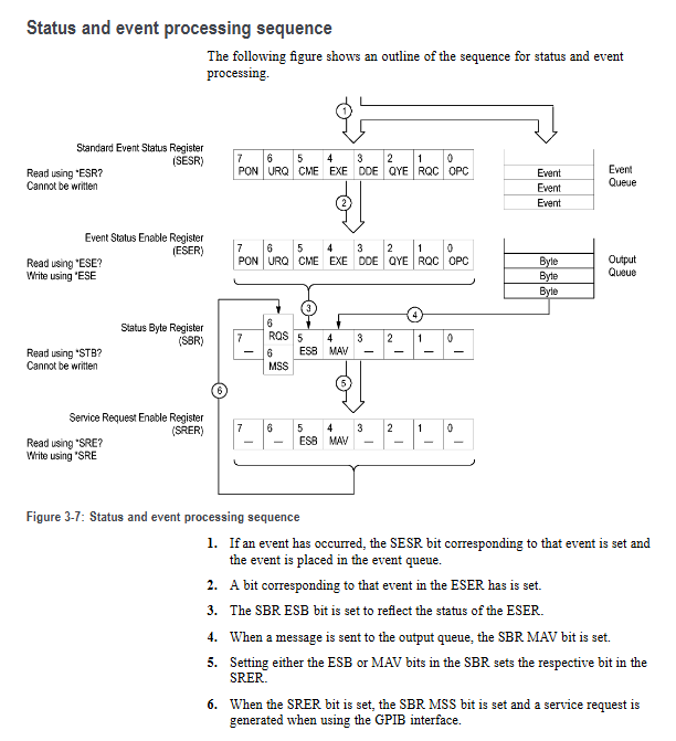
Status and Event System: Monitoring Instrument Operation
1. Four major register groups
(1) Status Byte Register (SBR)
Function: Summarize all 8-bit registers of states through * STB? Query;
Key position definition:
Bit7 (OSS): Operation status summary (events after OENR mask);
Bit6 (MSS/RQS): Main status summary (with service requests);
Bit5 (ESB): Standard Event Summary (SESR has new events);
Bit4 (MAV): Message available (output queue with data);
Bit3 (QSS): Suspicious Status Summary (Events after QENR Mask).
(2) Standard Event Status Block (SESB)
Contains two registers:
SESR (Standard Event Status Register): Record power, error, and other events through ESR? Query;
ESER (Event Status Enable Register): Mask SESR events, set through * ESE.
SESR key position:
Bit7 (PON): Power on;
Bit5 (CME): Command error (such as syntax error);
Bit4 (EXE): Execution error (such as parameter out of range);
Bit0 (OPC): Operation completed (triggered by OPC command).
2. Two types of queues
(1) Output queue
Function: FIFO structure, storing response data for query commands;
Trigger condition: After the query is executed, the data is stored in the queue, and the MAV bit of SBR is set to 1;
Clearing rule: Automatically clear when receiving new commands/queries, unread data will result in errors.
(2) Event queue
Function: FIFO structure, storing instrument events (errors, status changes, etc.);
Capacity limit: Up to 32 events, if exceeded, replace the 32nd event with -350, "Queue Overflow";
Query method: SYSTem: ERRor [: NEXT]? (Read the next one) SYSTem:ERRor:ALL? (Read all).
Appendix Key Content
1. Appendix A: Character Table
A hexadecimal/decimal value that covers 7 ASCII characters, including control characters (such as LF=0A hex) and printable characters (such as A=41 hex), used as a character encoding reference for command transmission.
2. Appendix B: Original Socket Specification
Define communication parameters for the Raw Socket protocol:
Port number: 5025 (default);
Data format: ASCII, with each line terminated by n;
Timeout setting: It is recommended that the client set a 10 second timeout to avoid disconnection.
3. Appendix C: Factory Initialization Settings
List the default values for all parameters, such as:
Clock source: INTernal;
Sampling rate: AWG70001=50GS/s, AWG70002=25GS/s;
Trigger mode: ASYNChronous;
Output status: OFF (all channels are closed).
- OMRON
- ABB
- General Electric
- EMERSON
- Honeywell
- HIMA
- ALSTOM
- Rolls-Royce
- MOTOROLA
- Rockwell
- Siemens
- Woodward
- YOKOGAWA
- FOXBORO
- KOLLMORGEN
- MOOG
- KB
- YAMAHA
- BENDER
- TEKTRONIX
- Westinghouse
- AMAT
- AB
- XYCOM
- Yaskawa
- B&R
- Schneider
- KONGSBERG
- NI
- WATLOW
- ProSoft
- SEW
- ADVANCED
- Reliance
- TRICONEX
- METSO
- MAN
- Advantest
- STUDER
- DANAHER MOTION
- Bently
- Galil
- EATON
- MOLEX
- DEIF
- B&W
- ZYGO
- Aerotech
- DANFOSS
- Beijer
- Moxa
- Rexroth
- Johnson
- WAGO
- TOSHIBA
- BMCM
- SMC
- HITACHI
- HIRSCHMANN
- Application field
- XP POWER
- CTI
- TRICON
- STOBER
- Thinklogical
- Horner Automation
- Meggitt
- Fanuc
- Baldor
- SHINKAWA
- Other Brands
- UniOP
- KUKA
- Iba
- Beckhoff
- ADLINK
-
 Basler Electric BE3-32-3AC Reverse Power Relay 9 1376 00 105
 -
 Basler Electric BE3-25-1A1N4 Synch Check Relay 9319100100
 -
 Basler Electric SR4A-2B15B3A Static Voltage Regulator
 -
 Basler Electric SR4A-2B15B3E Static Voltage Regulator
 -
 Basler Electric 9170818100 Solid State Protective Relay
 -
 Basler Electric AEC63-7 Analog Excitation Controller
 -
 Basler Electric 17483 Auxiliary Module
 -
 Basler Electric BE1-59 Over Voltage Relay
 -
 Basler Electric 21600-101 Control Module
 -
 Basler Electric KR2F Generator Voltage Regulator 9056600100
 -
 Basler BE1-CDS Current Differential System
 -
 Basler Electric CBS 212 Current Boost System 9 2650 00 100
 -
 Basler Electric IFM-150 Firing Circuit Chassis
 -
 Basler Electric BE1-60 Voltage Balance Relay C1F A1P D0C3F
 -
 Basler Electric BE1-32R Power Relay A2E D1R A0N0F
 -
Basler Electric BE1-32R Power Relay A2E D1R A0N0F
-
 Basler Electric 8650C80G01 Isolation Transducer PCB Board
 -
 ETEL EA-P2M-300-4/7.5A-0100-01 AccurET Modular 300 Servo Drive
 -
 Basler Electric 87T Transformer Differential Relay
 -
 Basler Electric BE-6868 Power Transformer 5950007559202
 -
 Basler Electric PRS250 Veri-Sync Relay 9088800102
 -
 Basler Electric SCP-250-G-60 VAR Power Factor Controller
 -
 Basler DECS-150 AVR 1NS2V1N1S Voltage Regulator
 -
 Basler UFOV 260A Under Frequency Overvoltage Module
 -
 Basler MOC2 199 Motor Operated Control – Overview and Setup
 -
 Basler BE3-49R-5K5A1 Temperature Relay – Complete Guide
 -
Basler BE 20035 001 Transformer – Technical Data and Installation
-
 Basler BE 02727 001 Transformer – Specifications and Usage
 -
 Basler BE127 Under Voltage Relay – Features and Application Guide
 -
Basler CBS377 Current Boost System – Complete Technical Guide
-
 Basler BE1-87G P/N 9170818100 Differential Relay – In-Depth Specs
 -
Basler BE1-87G Generator Differential Relay – Technical Overview
-
Basler Electric SR4A2B16 SVR Static Voltage Regulator – Complete Guide
-
 Basler Electric 9261500101 Power Supply Module
 -
 Basler Electric AEM-2020 Analog Expansion Module
 -
Basler Electric DGC-2020 Digital Genset Controller 51BRBNEAH001
-
Basler Electric BE1-59N Ground Fault Overvoltage Relay
-
 Basler Electric BE1-59N-A5E-E1L-N0S1F Neutral Overvoltage Relay
 -
Basler Electric MOC2499 Motor Operator Control Potentiometer 9072300430
-
 Basler Electric BE1-50/51M Overcurrent Relay
 -
 Basler Electric 9148100106 MOC3502 Solid State Relay 250VDC 0.25A
 -
 Basler Electric CBS 212 Current Boost System 9265000100
 -
 Basler Electric 10493002 Control Module
 -
Basler BE1-32R D3E E1R A0N1F Power Relay
-
 Basler SR8A2B15B3A Static Voltage Regulator
 -
 Basler IFM-105 Firing Circuit Chassis 9324100105
 -
Basler SR4A2B05B3A Static Voltage Regulator
-
 Basler BE151G1EB6PB0N0F Protective Relay
 -
Basler BE1-59 Electric Over Voltage Relay
-
 Basler 277 Static Programmable Powerline Carrier Channel
 -
 Basler BE1-32R D1E A1P A0N1F Power Relay
 -
Basler SR4A1B07B3A Static Voltage Regulator
-
 Basler Electric BE1-700 Digital Protective Relay
 -
Basler Electric SR8A-2B01B3A Static Voltage Regulator
-
 Basler Electric SR4A-2B01B3E Static Voltage Regulator
 -
 Basler Electric 9017709102 PC Board
 -
Basler Electric SR4A-2B01B3A Static Voltage Regulator
-
 Basler Electric PRS-250 Veri-Sync Relay
 -
 Basler Electric 9066800102 Excitation Support System
 -
Basler Electric BE1-87G Generator Differential Relay 9 1708 18 100
-
 Basler Electric 36T865-2 BE03752001 Power Supply
 -
 Basler Electric M-300 149D940G02 Power Supply
 -
 Basler Electric ACA2040-25GM 4Mp 25Fps Area Scan Camera
 -
 Basler BE1-87G-S1A-A1C-A0N0 Differential Relay
 -
Basler SR8A-2B06B3E Static Regulator SR8A2B06B3E
-
 Basler SCP-210 Frequency Controller 9095400100
 -
 Basler BE1-59-A3E-A1J-N1N3F Overvoltage Relay BE159A3EA1JN1N3F
 -
Basler 9 2011 11 100 Bracket Mounted Terminal Unit
-
Basler 9 1606 00 101 Voltage Regulator
-
 Basler CBS-377 Current Boost System 9109600102
 -
 Basler 8650C72 Exciter Control Module PCB Rev 5
 -
 Basler C2EE1PA0N1F BE1-32R Reverse Power Relay
 -
 ADLINK HPCI-14S12U - Industrial Control Backplane 12PCI Backplane PCI-14S Passive Backplane
 -
-0010.png) ADLINK PCIe-GIE74C - image acquisition card 4-CH GigE Vision PoE+ Frame Grabber
ADLINK PCIe-GIE74C - image acquisition card 4-CH GigE Vision PoE+ Frame Grabber -
-0010_1.png) ADLINK PCI-8164 - control card 4-Axis Advanced Motion Controller Board
ADLINK PCI-8164 - control card 4-Axis Advanced Motion Controller Board -
 ADLINK PCIe-U304 - 4 Port USB3 PCIe Frame Grabbers USB Screw Hole Card
 -
 ADLINK PCI-9112 - Multi-Function Data Acquisition Card DAQ Card
 -
 ADLINK PCI-7432 - 51-12013-0A50 4-CH Isolated Numérique I/O PCI Cartes Digital I/O Card
 -
 ADLINK PCA-6106P3-0C1 REV.C1 - backplane 6-Slot Passive Backplane Board
 -
 ADLINK PCI-7224 - 24-CH Opto-Isolated Digital I/O PCI Board
 -
 ADLINK CPCI-7433R(G) - Digital Input Board Rear I/O CompactPCI Card
 -
 ADLINK EBP-13E4 - 51-46703-0A30 Industrial PC Backplane Passive Backplane
 -
 ADLINK PCIE-HDV62 - Image acquisition card High Definition Video Frame Grabber
 -
 ADLINK EBP-13E4 - 51-46703-0A30 Industrial Backplane Board Passive Backplane
 -
 ADLINK 90111-B1 / CPCI-6770 - PCB CPU MODULE CompactPCI Single Board Computer
 -
 ADLINK PCI-7248 - DATA ACQUISITION PCI CARD 48-CH Parallel Digital I/O Board
 -
 ADLINK PCI-7230 - 51-12003-0a50 board PCI7230 32-CH Isolated Digital I/O Card
 -
 ADLINK PCI2A000CB - 51-20000-0B30 Multi-Function DAQ Card Baseboard
 -
 ADLINK PCI-8134-005 - 4-Axis Motion Controller Card
 -
 ADLINK PCI-7224 - 24-CH Opto-Isolated Digital I/O PCI Card
 -
 ADLINK PCI-7434 - 64-CH Isolated Digital Output Card
 -
 ADLINK PCI-8132 - motion control card 2-Axis Servo & Stepper Controller
 -
 ADLINK PCI-8134 - Motion Controller PCI Card 4-Axis Controller Board
 -
 ADLINK PCI-8164 - Motion Control Card 51-12406-0A40 4-Axis Controller
 -
 ADLINK 51-12001-0C20 - Circuit Board Data Acquisition Interface Module Hardware
 -
 ADLINK NuPR0-840 - industrial control motherboard Full-Size PICMG CPU Board
 -
 ADLINK PCI-7444 - 51-12023-0A10 card 128-CH Isolated Digital Output Board
 -
 ADLINK PCI-1612B - data acquisition card 4-Port RS-232/422/485 Serial Communication Card
 -
 ADLINK PCI-6208V 009 - 8/16-CH 16-Bit Analog Output Cards PCB-I-E-482=6BX3
 -
 ADLINK NUPRO-935A/LV - industrial control motherboard Full-Size PICMG SBC Board
 -
 ADLINK PCI-9114DG - Multi-Function DAQ Card Data Acquisition PCI Card
 -
 ADLINK ACL-7130 - Data acquisition card Isolated Digital I/O Board
 -
 ADLINK ABX-6300D-4E1-BP - board ABX6300D4E1BP Video Interface Expansion Card
 -
 ADLINK CPCI-6940 - CPCI-6940/D1539/M16-0(EA)-000E 6U CompactPCI Processor Board
 -
 ADLINK NuPRO-760 - industrial control motherboard Half-Size PICMG SBC CPU Board
 -
 ADLINK IMB-M42H (G)-0020 - industrial control motherboard LGA1155 Micro-ATX Mainboard
 -
 ADLINK RTV-24 / PCI-MP4S - 51-12519-1C30 4-Channel Real Time Video Capture Board
 -
 ADLINK PCI-8134 - 4-Axis Servo & Stepper Motion Controller Card
 -
 ADLINK MXC-6101D - V.PC000.002.ST.00 Box PC Configurable Embedded Computer
 -
.png) ADLINK PCI-8134A - 51-12421-0A10 Motion Control Card 4-Axis Controller Card
ADLINK PCI-8134A - 51-12421-0A10 Motion Control Card 4-Axis Controller Card -
 ADLINK DIN-100S / DIN-100SA1 - Technology SCSI-II TB 100-PIN Terminal Block Board
 -
.png) ADLINK DIN-812M001 / DIN812M001 - 51-14034-0A1 51140340A1 Terminal Module Breakout Interface
ADLINK DIN-812M001 / DIN812M001 - 51-14034-0A1 51140340A1 Terminal Module Breakout Interface -
_1.png) ADLINK PCI-8164 - Servo motion control 4-Axis Advanced Controller Card
ADLINK PCI-8164 - Servo motion control 4-Axis Advanced Controller Card -
 ADLINK PCIe-GIE64 - Acquisition card GigE Vision PoE+ Frame Grabber
 -
 ADLINK M-302 - Industrial control motherboard ATX PC Board Mainboard
 -
 ADLINK PCI-8134 - Motion Controller PCI Card 4-Axis Controller Board
 -
 ADLINK PCI-RTV24 - Image capture card Analog Video Frame Grabber
 -
 ADLINK PCI-8102 - Motion control card 2-Axis Servo & Stepper Controller Board
 -
 ADLINK PCI-9112 REV.B1 - Card Multi-Function Data Acquisition Card
 -
 ADLINK HSI-DI32-M-N / HSL-TB32-M-DIN - Discrete I/O MODULE Distributed Automation Module System
 -
 ADLINK PCI-7296 - IO card REV.A3 96-CH Parallel Digital I/O Card
 -
-0020.png) ADLINK DIN-814P-A4 / 814Y - terminal board Motion Control Interface Block
ADLINK DIN-814P-A4 / 814Y - terminal board Motion Control Interface Block -
 ADLINK DIN-814P-A4 - 51-14056-0A10 PCB-I-E-2736=ZA01 Screw Terminal Board Breakout
 -
 ADLINK M-322 - motherboard Industrial Control Computer Mainboard
 -
 ADLINK NUPRO-406 REV:B1 - industrial control motherboard Full-Size PICMG CPU Board
 -
 ADLINK AMP-204C - card DSP-Based 4-Axis Advanced Pulse-Train Controller
 -
 ADLINK HPCI14S REV.B1 - industrial computer baseboard 14-Slot Passive Backplane
 -
 ADLINK PCI-7250 - 8-CH Relay Output & 8-CH Isolated DI PCI Card


