MITSUBISHI A-series PLC Troubleshooting Replacement
1. Control cabinet processing
Use conductive metal cabinets to maintain good electrical contact between panels (remove paint).
Flat braided wires are used to connect multiple points between the cabinet door and the main body, reducing high-frequency impedance.
The cross-sectional area of the cabinet grounding wire should be ≥ 22mm ², and the length should be as short as possible.
Cabinet opening diameter ≤ 10cm to prevent high-frequency noise radiation.
2. Connection between power supply and grounding wire
Set up a grounding point near the power module and connect the LG and FG terminals with the shortest wire (≤ 30cm).
For A1S61P/A1S62P/A1S63P, a noise filter needs to be installed at the input end (recommended SCHAFFNER FN343-3/01 or TDK ZHC2203-11).
For CE compatible models (A1S61PEU, A1S62PEU, A1S61PN, A1S62PN), no external filter is required, but LG and FG must be short circuited (unless otherwise specified).
Twist the power cord and ground wire together to enhance common mode noise discharge.
3. Signal cable shielding
All I/O signal lines and communication lines (RS-232C, RS-422, etc.) leading out of the control cabinet must use shielded cables.
The shielding layer contacts the cabinet grounding through a large area of metal clips (welding leads cannot be used due to high high-frequency impedance).
For MELSECNET/II modules (such as A1SJ71AR21), a three coaxial cable must be used and a ferrite magnetic ring (TDK ZCAT3035 is recommended) must be installed at the cable outlet.
The AUI cable of Ethernet module A1SJ71E71-B5 needs to be stripped of insulation and grounded extensively.
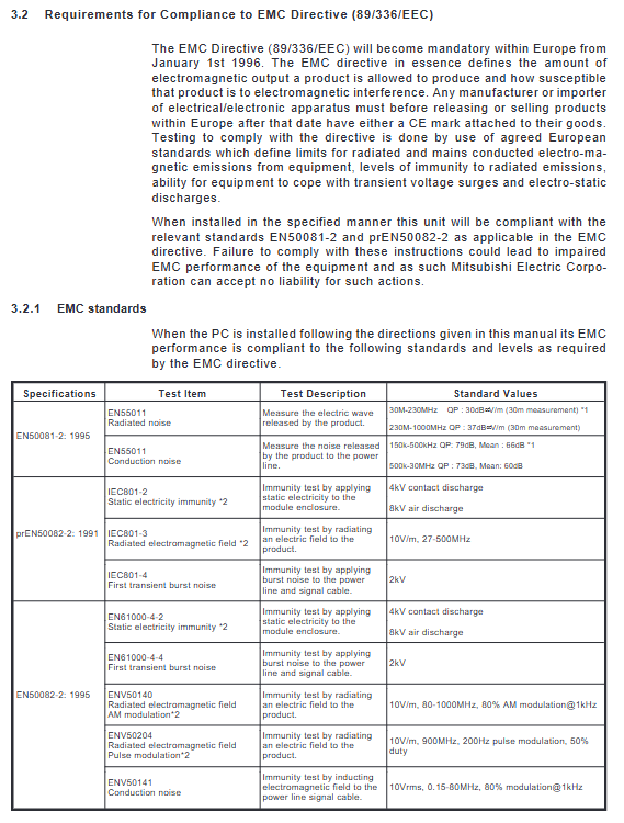
Attention: If shielded cables are not used or shielded grounding is poor, the immunity will decrease from 2kV (IEC801-4) to below 1kV, which may cause false signals.
Selection and replacement of power module and I/O module
1. Power module replacement guide
Prototype Number Recommended Replacement (CE Compatible) Remarks
A1S61P (100-120VAC) A1S61PN (100-240VAC) 5V/5A output, requires an external filter
A1S62P (200-240VAC) A1S62PN (100-240VAC) 5V/3A + 24V/0.6A
A1S63P (24VDC input) without CE compatibility model requires external SELV power supply
Replacement precautions:
Overcurrent protection: When the 5V output current exceeds 5.5A (A1S61P) or 3.3A (A1S62P), the power module will automatically turn off the output and turn off the LED. At this point, the load short circuit must be eliminated before power can be restored.
Overvoltage protection: If the 5V voltage rises to 5.5-6.5V, the protection will activate. Power off and then power on to reset. If it still cannot be restored, replace the power module.
Allowable instantaneous power down time: A1S63P is about 20ms under 24VDC input; A1S61P/A1S62P is over 20ms under AC input.
2. Key points for replacing input modules
The rated voltage of AC input modules (such as A1SX10, A1SX20) is 100-120VAC or 200-240VAC. It should be noted that CE compatible models (such as A1SX10EU, A1SX20EU) have a dielectric strength of 1780VAC and the same operating temperature range.
DC input modules (such as A1SX40, A1SX41, A1SX80, etc.) support 12/24VDC, input current 3-7mA, and response time is usually 10ms (high-speed models such as A1SX42 can reach 0.1ms). Attention should be paid when replacing:
Source/Drain Type: The A1SX80 series supports both sink and source connections, while the A1SX40 only supports the sink type.
Response speed: If the original system uses high-speed counting (such as encoder signals), a model with a response time of ≤ 0.2ms (such as A1SX42) must be selected, otherwise pulses will be lost.
3. Output module replacement
Relay output (A1SY10, A1SY14, A1SY18A): Contact capacity 240VAC/24VDC, 2A/point, 8A/common terminal. When replacing, pay attention to the higher dielectric strength (2830VAC) of CE compatible models (A1SY10EU, A1SY14EU, A1SY18AEU). The lifespan of the relay is 20 million mechanical cycles and 100000 electrical cycles (rated load).
Controllable silicon output (A1SY22, A1SY28A): suitable for AC loads, with a response time of approximately 1ms+0.5 cycles. When replacing, pay attention to the load current (0.6A/point, 2.4A/common terminal).
Transistor outputs (A1SY40, A1SY41, A1SY42, etc.): used for DC loads, with a response time of 2ms, and some high-speed types (such as A1SY71) can reach 2ms. Special attention should be paid to:
Output current: A1SY40 is 0.1A/point, A1SY42 is 0.5A/point, A1SY50 is 2A/point. When replacing, be sure to check the original load current to avoid overloading and burning out.
Surge suppression: The transistor output is internally integrated with a Zener diode, but for inductive loads, it is still recommended to use an external parallel freewheeling diode.
Fuse: Most transistor output modules do not come with fuses and require external installation (fast melting is recommended).
Code of practice for electrical wiring
1. Power wiring
Connect the live wire (L) and neutral wire (N) of the AC power supply to the corresponding terminals of the power module. LG is functional grounding, FG is protective grounding. FG must be connected to the grounding bar of the control cabinet.
For A1S63P (24VDC input), an external power supply that complies with SELV (Safety Extra Low Voltage) must be used, with the 24V positive pole connected to "24V" and the negative pole connected to "COM".
- OMRON
- ABB
- General Electric
- EMERSON
- Honeywell
- HIMA
- ALSTOM
- Rolls-Royce
- MOTOROLA
- Rockwell
- Siemens
- Woodward
- YOKOGAWA
- FOXBORO
- KOLLMORGEN
- MOOG
- KB
- YAMAHA
- BENDER
- TEKTRONIX
- Westinghouse
- AMAT
- AB
- XYCOM
- Yaskawa
- B&R
- Schneider
- KONGSBERG
- NI
- WATLOW
- ProSoft
- SEW
- ADVANCED
- Reliance
- TRICONEX
- METSO
- MAN
- Advantest
- STUDER
- DANAHER MOTION
- Bently
- Galil
- EATON
- MOLEX
- DEIF
- B&W
- ZYGO
- Aerotech
- DANFOSS
- Beijer
- Moxa
- Rexroth
- Johnson
- WAGO
- TOSHIBA
- BMCM
- SMC
- HITACHI
- HIRSCHMANN
- Application field
- XP POWER
- CTI
- TRICON
- STOBER
- Thinklogical
- Horner Automation
- Meggitt
- Fanuc
- Baldor
- SHINKAWA
- Other Brands
- UniOP
- KUKA
- Iba
-
 Keyence LJ-V7000 Controller Laser Profiler
 -
 Siemens 6EP3437-8SB00-0AY0 Power Supply 20A
 -
 Pasaban MC-2006 03 CAN Bus PLC Card
 -
 ETAS ES600.2 PLC Module Prototyping
 -
 ABB ACS800-01-0005-3+P901 Frequency Converter
 -
 Omron NX102-1100 PLC Module Machine Automation
 -
 Square D BMXCPS3500 PLC Power Supply Module
 -
 Allen-Bradley 96657704 Fiber Optic Converter 1771-AF
 -
 Corcom 20VK1 Power Line Filter
 -
 Novellus 2805-11407 PLC Rack Assembly
 -
 Sick RLY3-EMSS100 Safety Relay Module
 -
 Microchip PIC12F508-I/P Microcontroller
 -
 Fanuc A02B-0098-B511 Motherboard
 -
 Merlin Gerin PB80 PLC Rack Module
 -
 ABB Pluto S20 V2 CFS Safety PLC
 -
 Honeywell TK-PRR021 Redundancy Module
 -
 B&R 7XX419L.50-1 Bus Controller
 -
 Mitsubishi NV400-SW 3P 300A Breaker
 -
 B&R X20AT2222 Temperature Module
 -
 Corcom 20VK1 EMI RFI Filter
 -
 Novellus 2805-11407 PLC Rack Assy
 -
 Mitsubishi FXAOM01BD Analog Output Module 4CH
 -
 NORIS A1-91 PCB Rack Module A1-91-4 A1-91-5 A1-91-6 A1-91-7 A1-91-8
 -
 Omron ZFV-SC50 Smart Camera Vision Sensor
 -
 Schneider Electric EOCR-PMZ Motor Protection Relay
 -
 B&R X20 SO 6300 PLC Module Safety Output
 -
 Mitsubishi A2ACPU21-S1 CPU Module MELSEC
 -
 Siemens 6ES7405-0KA02-0AA0 PS405 10A Power Supply
 -
 Samsung PVU-2424 Power Supply Unit DC24V 24W
 -
 ATTO controlSYS ATT0-CPU44 PLC with Display
 -
 Lenze EPZ-10203 CANPT010W3E Absolute Encoder
 -
 GE IS215WEMAH1A+IS210BPPBH2CAA Mark VIe Embedded Processor and Backplane Power Distribution Board
 -
 GE IS215AEPAH1CH+IS210BPPBH2CAA Mark VIe Application Processor and Backplane Power Distribution Board
 -
 GE IS215WECAH1B+IS210BPPBH2CAA Mark VIe Control Platform
 -
 GE PCM Regulator for EX2100e Power Conversion Module 151X1235DB15SA1
 -
 Lenze ECSEA048C4B servo drive
 -
 ABB PM665 3BDS005799R1 redundant CPU module
 -
 BAUMULLER b maXX 3000 Servo Controller BM3401-LIFBO-ACOOOCB-G-02-O-02
 -
 R&S EPL10200-W EMI Test Receiver
 -
 Schneider M522220000 16 way relay output module
 -
 ABB 3HAC031851-001 SMB Unit Technical Manual
 -
 Fuji NB1U56X-01 Programmable Controller Guide
 -
 Siemens 6AG1153-2BA02-7XB0 SIPLUS IM 153-2 Manual
 -
 Beckhoff EL6631 PROFINET Terminal Manual
 -
 Lenze E82EV302-4C Frequency Inverter Manual
 -
 Siemens 6SE7038-6EK84-1JC2 IGD8 Board Specifications
 -
 Pilz 774595 Safety Relay Specifications
 -
 Fanuc A20B-8200-0847 PLC Board Specification
 -
 Allen Bradley 1785-L60B/E PLC CPU Manual
 -
 PASABAN MC-2006 03 PLC Card Specifications
 -
 B&R X20CP1382 PLC Control Module X20 CPU
 -
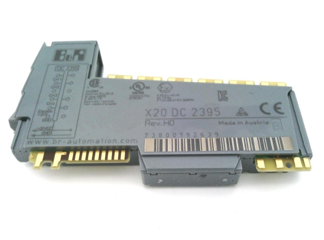 B&R X20DC2395 PLC Module Digital Output
 -
 AS-2P-70M-B Industrial PLC Communication Cable 70M
 -
 Siemens 6ES7136-6BA00-0CA0 PLC Module ET 200SP
 -
 Siemens 1FK7083-5AF71-1EB3 Servo Motor SIMOTICS S
 -
 WAGO 750 Series I/O Modules 750-842 750-530 750-430 750-602 750-514 750-600
 -
 Microchip TC9401CPD F/V Converter 100kHz 14DIP
 -
 Mitsubishi GT2310-VTBA GT2310-VTBD HMI Touch Screen 10.4 Inch
 -
 Siemens 3RT2036-1AN20 AC Contactor SIRIUS
 -
 Mitsubishi GT2708 HMI Touch Screen GT2708-VTBA VTBD STBA STBD
 -
 Siemens 6FC5110-0CB01-0AA0 CNC PLC CPU
 -
 ABB SINT4130C PCB Board
 -
 Omron NX1P2-1040DT PLC Controller
 -
 Fuji FRN3.7C1S-2J VFD
 -
 PLC-60/75 /E2UK Shielded Braided Cable
 -
 Omron CJ1W-NC434 Position Control Unit
 -
 Omron NX-AD2208 Analog Input Module
 -
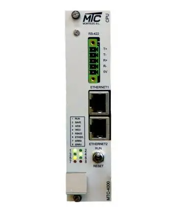 PASABAN MC-2006 03 PLC Card
 -
 Schneider 9038CR34 Pressure Switch
 -
 Pilz 240340 Safety Control Module
 -
 Mitsubishi A2NCPU Programmable Controller MELSEC
 -
 Mitsubishi Alpha XL Alarm Modem M20 Expansion
 -
 AutomationDirect D0-06DD2-D PLC DL06 Controller
 -
 Toshiba COMW01-21 PCB Control Board Turbine
 -
 Siemens 6FX1122-1AC02 Coupling Module SINUMERIK
 -
Omron CVM1-CPU21-V2 CPU Unit Programmable
-
 Beckhoff EL7041 Stepper Motor Terminal EtherCAT
 -
 B&R X20AI4622 Analog Input Module 4 Channels
 -
 OAT PMC25.2-003 Programmable Controller Module
 -
 Fanuc A16B-2200-0350 Graphic Board Series 16
 -
 Eaton Cutler Hammer 6-26-2 Contactor Contact Kit
 -
 Omron D4SL-NSK10-LK-K Safety Switch
 -
 Siemens C98043-A7001-L24 CUD1 Control Board
 -
 Mitsubishi A2NCPUR21-S1 PLC Module
 -
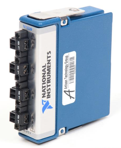 National Instruments NI-9242 4-channel analog input module
 -
 BEMAC UST-202-D PLC Interface Board
 -
 Omron CJ1W-DA08C Analog Output Module
 -
 Mitsubishi QX521 CNC Interface Board
 -
 Schneider BMEP586040 High-Performance PLC Processor
 -
 Emerson 5X00875G01 Process Control PLC
 -
 Siemens SIMODRIVE 611 Power Module 6SN1145-1AA01-0AA0
 -
 Siemens 840C NC-CPU 486DX4 6FC5110-0BB04-0AA1
 -
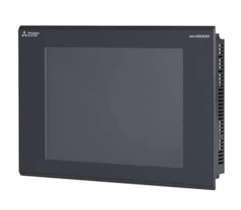 Mitsubishi GT2708 Series Operation Panel Touch HMI
 -
 Fanuc A04B-0103-C220 Programmable Controller Module
 -
 IFM CR2530 Programmable Controller for Mobile Automation
 -
 Omron FH-3050 Vision Controller i7-2715QE High Performance
 -
 National Instruments NI-9242 4-Ch Analog Input Module
 -
 B&R X20AI4632 Analog Input Module 4 Channels
 -
 Pilz 773600 Input Module Safety Automation
 -
 Panasonic AFPX-C60P Programmable Controller PLC
 -
 Siemens 6ES7414-2XL07-0AB0 S7-400 CPU Manual
 -
 Cutler Hammer WM34V Interlock Kit Manual
 -
 Pilz 777587 Safety Relay Specifications
 -
 Omron CJ2H-CPU64-EIP CPU Module Manual
 -
 B&R X20AI1744-3 Analog Input Module Guide
 -
 Schneider LC1G185BEEA Contactor Specification
 -
 Sharp LM64P101 LCD Screen Specifications
 -
 B&R X20AT4222 Temperature Module Guide
 -
 Mitsubishi A2UCPU-S1 Controller Specifications
 -
 Stein Sohn E 083.1 Rack Module Technical Guide
 -
 Omron CK3W-AX1515N Motion Controller
 -
 Schneider TSXP572634M PLC Processor
 -
 Epson RAIOC-33 Programmable Controller
 -
 GRID T&D iRTUe-D1R1-W.125 I/O Module
 -
 Fanuc A20B-2002-0520 Control Board
 -
 B&R X20IF1030 Interface Module
 -
 Schneider ATV320U55N4B VFD
 -
 Omron NA5-9W001B-V1 HMI Touchscreen
 -
 Mitsubishi A2NCPU PLC CPU Unit
 -
 Omron CJ2M-CPU34 PLC CPU Unit
 -
 Omron NS12-TS01B-V2 Touch Screen HMI
 -
 Mitsubishi FX3GE-24MT/ESS PLC Controller
 -
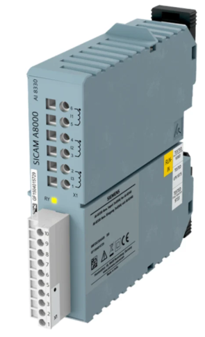 Grundig NEA02 AES 0 PLC I O Module
 -
 Beckhoff EP3204-0002 EtherCAT Box Module
 -
 Mitsubishi MDS-A-CV-220 Power Supply Unit
 -
 MCX20B2 080G0330 Motion Controller
 -
 Toyo Keiki P CARD5 Interface Board YH-212
 -
 National Instruments NI 9242 Analog Input Module