
GE FANUC S2K series independent motion controller
FANUC S2K series independent motion controller
Equipment Overview
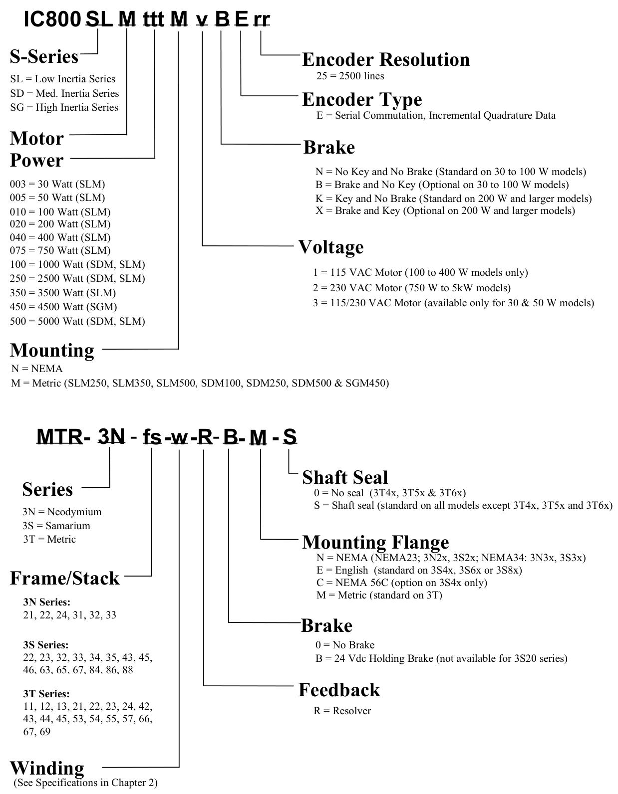
The FANUC S2K series is a high-performance standalone brushless servo or stepper amplifier series that integrates motion controllers and user configurable I/O functionality. The controller can be configured with a rotary transformer or a serial encoder motor feedback model. The encoder based S2K servo model can only be used in conjunction with GE Fanuc S series (SLM, SDM, or SGM) servo motors. The S2K rotary transformer feedback servo controller uses GE Fanuc MTR series (3N, 3S, or 3T) servo motors or third-party motors with appropriate ratings and rotary transformer specifications.

The servo model supports continuous stall torque of 0.84-478 in lb (0.095-54 Nm), while the stepper model supports holding torque of 144-3074 oz in (16.3-21.7 Nm). The servo controller model includes four 230 VAC ratings of 4.3, 7.2, 16, and 28 ampere continuous, as well as two 460 VAC ratings of 7.2 and 20 ampere continuous (the 460 VAC model only provides feedback for the rotary transformer). The peak current of the 230 VAC servo model is twice the continuous rated value, while the 460 VAC servo model is 1.5 times the continuous rated value. The rated value of the stepper controller is 5 amperes.
Support DeviceNet ™ The PROFIBUS communication model includes 14 discrete I/O points. 4.3 and 7.2 ampere servo models and stepper models can also provide 21 I/O points instead of DeviceNet or PROFIBUS communication. All drivers are capable of supporting Modbus/RTU protocol. If the optional Modbus adapter (product number IC800MBUSADP) is used, the standard RS-232 serial port can be used for multi-point applications. This adapter is an externally installed multi-point RS-232 to RS-485 serial port converter.
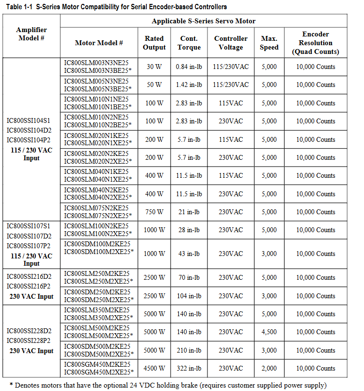
The S2K series controller is optimized for use with GE Fanuc S series or MTR series servo and stepper motors. If the motor and amplifier are not properly matched, overload and possible component damage may occur. Tables 1-1 to 1-3 show the recommended pairing of components.
The S2K series stepper controller requires a single-phase 115 VAC power supply. The S2K series servo controller models rated at 230 VAC and 4.3 or 7.2 amperes can operate on 115 VAC single-phase or 230 VAC three-phase, while all other models are rated for three-phase input. The 230 and 460 VAC models are designed to operate from three-phase power sources, but can be used with single-phase power sources.
The S series servo motors optimized for the S2K series controller range from 30 W to 5 kW and are rated at 230 VAC to achieve full speed. Using a 115 VAC power supply will result in a reduced operating speed of approximately half of the rated speed.
The 30 to 1000 watt S series servo motors (SLM models only), MTR-3S and MTR-3N series, and all stepper motor models are designed with standard NEMA shaft and flange mounting configurations for easy installation onto existing gear reducers and couplings. The 750 watt S series motor is installed with a super large shaft diameter (0.625 inches) for NEMA 34 to handle the peak torque rating of this model. The S series motor models ranging from 1 to 5 kW (except for the SLM100 1kW motor) and all MTR-3T series motors have metric installation configurations.
All servo motors can be equipped with an optional 24 VDC holding brake. These brakes are spring set, electrically released models designed to maintain static loads. The user must provide a separate 24 VDC brake power supply. The 30-750 watt S series motor has a pigtail cable with a box type connector for connecting the motor power supply, encoder, and brake. The 1000 to 5000 watt S series motors have MS style connectors, and the brake power supply (if needed) is integrated with the motor power supply in a common connector/cable. The MTR series servo motors include MS type connectors for brake power input. The MTR-3N and MTR-3T series brake motors integrate the brake power supply and motor power supply into the same cable. The MTR-3S brake motor requires a separate brake power cable (CBL-30-BT).
The S2K series controller is configured and programmed using Motion Developer software on a personal computer. This software is an independent application that works in the Machine Edition software environment, providing tools for beginners to simplify programming and direct code input for advanced users.
Hardware Overview
Specifications
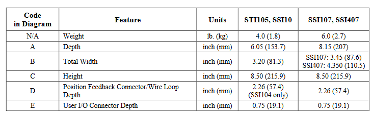
S2K series controllers are used together with S series or MTR series servo and stepper motors. This chapter contains each specification of these components. Table 2-1 shows the available hardware resources on the S2K controller.
Electrical specifications of stepper controller
The S2K stepper controller (IC800STI105xx) is suitable for use on circuits that can provide symmetrical amperes up to 5000 rms and a maximum voltage of 130 volts, when protected by RK5 class 15A fuses. Table 2-2 summarizes the maximum continuous input power requirements for stepper controllers. The actual input power and current are functions of the motor operating point and duty cycle.
Electrical specifications of servo controller
The servo controller model is suitable for use on circuits that can provide symmetrical amperes up to 5000 rms and a maximum voltage of 250 volts, when protected by RK5 fuses. Table 2-3 summarizes the maximum continuous input power requirements. The actual input power and current are functions of the motor operating point and duty cycle.
Environmental Specifications
Working temperature: 32 to 122 ° F (0 to 50 ° C)
Storage and transportation temperature: -40 to 176 ° F (-40 to 80 ° C)
Altitude: 3300 feet (1000 meters)
Relative humidity (non condensing): 5 to 95%
S2K Communication Specification
Serial communication: 1 available port, supports multi-purpose programming port, format RS-232, maximum addressable unit is 1, communication rate is 1200, 9600, 19200 or 38400 baud, protocol is ASCII or Modbus/RTU (optional Modbus RS-485 multipoint port converter is available); Product Code IC800MBUSADP
DeviceNet communication network: 1 port per unit, supports I/O slave message passing, position controller configuration file, and explicit peer-to-peer message passing, with a maximum of 64 nodes, input power requirement of 11-25 VDC @ 40 mA maximum, communication rates of 125, 250, or 500 KBaud, drop line length of up to 20 feet, fine line trunk length of up to 328 feet, maximum 328 feet at 500 KBaud, maximum 820 feet at 250 Kbaud, and maximum 1640 feet at 125 Kbaud
PROFIBUS communication network: 1 port per unit, supports PROFIBUS configuration files, multicast, and broadcasting, with a maximum addressable unit of 100, no input power requirements, and a communication rate of 9600; 19,200; 45,450; 93,750; 187,500; 500,000; 1,500,000; 3,000,000; 6,000,000; Or 12000000 baud, the maximum length of the serial data link is 3936 feet at 9.6 KBaud
Input and output specifications
Digital input and output: The working range is 12-24 VDC, with a maximum of 30 VDC. The interface format is optical isolation, and the source/drain can be configured by the user. The maximum input turn off voltage is 4 VDC, the minimum on voltage is 10 VDC, and the load is 2 k Ω. The maximum output on resistance is 35 ohms, the maximum load current is 100 mA, and the maximum turn off leakage current is 200 nA. The capture input response time is 30 µ S
Analog inputs: 2 available, operating range+/-10 VDC, resolution of 12 bits, input impedance of 50 k Ω
Analog output: 1 available, user programmable or configurable for speed, current or tracking error, operating range+/-10 VDC, resolution of 8 bits, output current of 5mA
Encoder input and output specifications
Auxiliary encoder input: 1 available, input voltage is 5, 12 or 15 VDC, line receiver is 26LS33, input format is single ended or differential sine or square wave orthogonal, pulse/direction or CW/CCW pulse, maximum line counting frequency is 3 MHz (12 MHz orthogonal),+5 or+12 VDC power output capacity is 0.5 ampere each
Encoder output: 1 available, output voltage is 5.2 VDC+/-1%, line driver is 26LS31, output format is differential square wave orthogonal, pulse/direction or CW/CCW pulse (see Section 3.6.6 (Tracking source format selected by EOT parameters), marked pulse width is 1/5000 of encoder revolutions, maximum line count frequency is 3 MHz (12 MHz orthogonal)
Motor feedback input
Motor encoder input (based on encoder model only): 1 available, resolution of 2500 lines per revolution, line receiver of 26LS33, data input format of differential, square wave, orthogonal, commutation input format of serial (S-series motor), maximum line count frequency of 3 MHz (12 MHz orthogonal)
Motor rotary transformer input (based on rotary transformer model only): 1 available, resolution of 4096 pulses per revolution, maximum speed of 15000 RPM, type of control transmitter, phase shift of ± 5.0 degrees at 5kHz, zero voltage<20 mV at 5 kHz, transformation ratio of 0.5
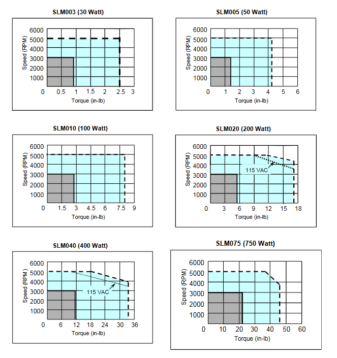
Motor speed/torque curve
Contains curves for MTR series stepper motors/controllers, S-series servo motors/controllers, and MTR series servo motors/controllers, demonstrating the relationship between motor speed and output torque. The motor can operate continuously at any speed and torque combination within a specified continuous operating range.
Servo motor derating based on ambient temperature
The S series motor generates continuous torque as shown in the speed/torque curve (Section 2.2.2) within a certain ambient temperature limit, depending on the motor model. The following curve describes the continuous torque derating required for operation at ambient temperatures above this rated value and up to a limit of 40oC. The intermittent torque available for each motor does not require derating.
The MTR series servo motors are rated at an ambient temperature of 25oC and are mounted on 10 "x 10" x 0.25 "aluminum heat sinks. For motors operating at higher ambient temperatures, the continuous torque of the motor must be reduced as follows: continuous torque at ambient temperature, toC=rated continuous torque x (155-t)/130.
Sealing of servo motor
The design of S series and MTR series servo motors complies with IP65 protection level (excluding cable connectors on S series 30-750 watt models). All MTR-3N, MTR-3S, MTR-3T1x, MTR-3T2x, and 1-5 kW rated S-series motors include shaft seals as standard functionality, while 30-750 watt S-series motors, MTR-3T4x, MTR-3T5x, MTR-3T6x, and all stepper motors do not provide shaft seals. Adequate precautions shall be taken when installing the motor to ensure proper protection from excessive liquid and spray exposure.
Servo motor maintains brake
The servo motor can be equipped with an optional integrated parking brake. The brake is designed for fail safe operation and must be powered by a 24 Vdc power supply to release the brake.
NEMA motor installation
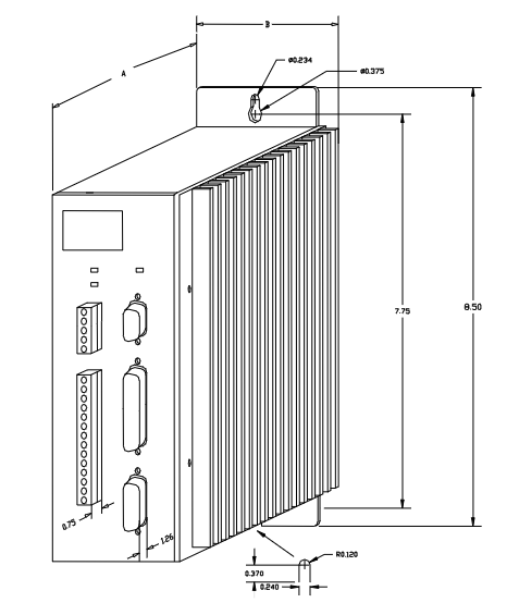
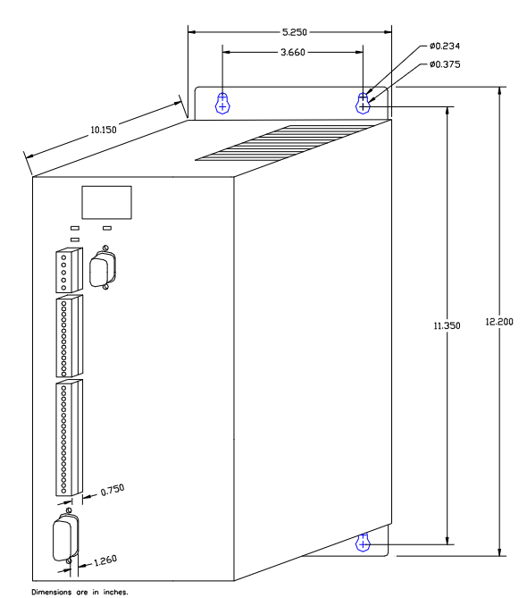
The MTR series and S series motors have installation configurations as shown in the table below. For dimensional information about these motors (including installation dimensions), please refer to the mechanical drawings in Chapter 3.
The MTR series stepper motors have standard NEMA shaft and flange installation configurations, as shown in Table 2-17 below. For the size information of these motors, please refer to the mechanical drawings in Chapter 3.
S series servo motor vibration test
These motors have two types of vibration tests, namely scanning test and resonance point test.
Scanning test: The motor undergoes a 5G variable frequency test on each of the three axes (X, Y, Z) for eight hours. For the purpose of these tests, the X-axis is parallel to the motor axis, the Y-axis is parallel to the encoder connector, and the Z-axis is at a 90 degree angle to X and Y. In this test, the vibration frequency increased from 20 to 3000 Hz within two minutes, and then decreased from 3000 to 20 Hz within two minutes. This pattern was repeated for eight hours.
Resonance point test: Firstly, identify the resonance frequency with the highest vibration when testing the motor in three directions (X, Y, Z) at a variable frequency of 5 G (20 to 3000 Hz). Then, the motor vibrates 10 million times in each direction (X, Y, Z) at the identified resonance frequency.
- OMRON
- ABB
- General Electric
- EMERSON
- Honeywell
- HIMA
- ALSTOM
- Rolls-Royce
- MOTOROLA
- Rockwell
- Siemens
- Woodward
- YOKOGAWA
- FOXBORO
- KOLLMORGEN
- MOOG
- KB
- YAMAHA
- BENDER
- TEKTRONIX
- Westinghouse
- AMAT
- AB
- XYCOM
- Yaskawa
- B&R
- Schneider
- KONGSBERG
- NI
- WATLOW
- ProSoft
- SEW
- ADVANCED
- Reliance
- TRICONEX
- METSO
- MAN
- Advantest
- STUDER
- DANAHER MOTION
- Bently
- Galil
- EATON
- MOLEX
- DEIF
- B&W
- ZYGO
- Aerotech
- DANFOSS
- Beijer
- Moxa
- Rexroth
- Johnson
- WAGO
- TOSHIBA
- BMCM
- SMC
- HITACHI
- HIRSCHMANN
- Application field
- XP POWER
- CTI
- TRICON
- STOBER
- Thinklogical
- Horner Automation
- Meggitt
- Fanuc
- Baldor
- SHINKAWA
- Other Brands
- UniOP
- KUKA
- Iba
- Beckhoff
- ADLINK
-
 Basler Electric BE3-32-3AC Reverse Power Relay 9 1376 00 105
 -
 Basler Electric BE3-25-1A1N4 Synch Check Relay 9319100100
 -
 Basler Electric SR4A-2B15B3A Static Voltage Regulator
 -
 Basler Electric SR4A-2B15B3E Static Voltage Regulator
 -
 Basler Electric 9170818100 Solid State Protective Relay
 -
 Basler Electric AEC63-7 Analog Excitation Controller
 -
 Basler Electric 17483 Auxiliary Module
 -
 Basler Electric BE1-59 Over Voltage Relay
 -
 Basler Electric 21600-101 Control Module
 -
 Basler Electric KR2F Generator Voltage Regulator 9056600100
 -
 Basler BE1-CDS Current Differential System
 -
 Basler Electric CBS 212 Current Boost System 9 2650 00 100
 -
 Basler Electric IFM-150 Firing Circuit Chassis
 -
 Basler Electric BE1-60 Voltage Balance Relay C1F A1P D0C3F
 -
 Basler Electric BE1-32R Power Relay A2E D1R A0N0F
 -
Basler Electric BE1-32R Power Relay A2E D1R A0N0F
-
 Basler Electric 8650C80G01 Isolation Transducer PCB Board
 -
 ETEL EA-P2M-300-4/7.5A-0100-01 AccurET Modular 300 Servo Drive
 -
 Basler Electric 87T Transformer Differential Relay
 -
 Basler Electric BE-6868 Power Transformer 5950007559202
 -
 Basler Electric PRS250 Veri-Sync Relay 9088800102
 -
 Basler Electric SCP-250-G-60 VAR Power Factor Controller
 -
 Basler DECS-150 AVR 1NS2V1N1S Voltage Regulator
 -
 Basler UFOV 260A Under Frequency Overvoltage Module
 -
 Basler MOC2 199 Motor Operated Control – Overview and Setup
 -
 Basler BE3-49R-5K5A1 Temperature Relay – Complete Guide
 -
Basler BE 20035 001 Transformer – Technical Data and Installation
-
 Basler BE 02727 001 Transformer – Specifications and Usage
 -
 Basler BE127 Under Voltage Relay – Features and Application Guide
 -
Basler CBS377 Current Boost System – Complete Technical Guide
-
 Basler BE1-87G P/N 9170818100 Differential Relay – In-Depth Specs
 -
Basler BE1-87G Generator Differential Relay – Technical Overview
-
Basler Electric SR4A2B16 SVR Static Voltage Regulator – Complete Guide
-
 Basler Electric 9261500101 Power Supply Module
 -
 Basler Electric AEM-2020 Analog Expansion Module
 -
Basler Electric DGC-2020 Digital Genset Controller 51BRBNEAH001
-
Basler Electric BE1-59N Ground Fault Overvoltage Relay
-
 Basler Electric BE1-59N-A5E-E1L-N0S1F Neutral Overvoltage Relay
 -
Basler Electric MOC2499 Motor Operator Control Potentiometer 9072300430
-
 Basler Electric BE1-50/51M Overcurrent Relay
 -
 Basler Electric 9148100106 MOC3502 Solid State Relay 250VDC 0.25A
 -
 Basler Electric CBS 212 Current Boost System 9265000100
 -
 Basler Electric 10493002 Control Module
 -
Basler BE1-32R D3E E1R A0N1F Power Relay
-
 Basler SR8A2B15B3A Static Voltage Regulator
 -
 Basler IFM-105 Firing Circuit Chassis 9324100105
 -
Basler SR4A2B05B3A Static Voltage Regulator
-
 Basler BE151G1EB6PB0N0F Protective Relay
 -
Basler BE1-59 Electric Over Voltage Relay
-
 Basler 277 Static Programmable Powerline Carrier Channel
 -
 Basler BE1-32R D1E A1P A0N1F Power Relay
 -
Basler SR4A1B07B3A Static Voltage Regulator
-
 Basler Electric BE1-700 Digital Protective Relay
 -
Basler Electric SR8A-2B01B3A Static Voltage Regulator
-
 Basler Electric SR4A-2B01B3E Static Voltage Regulator
 -
 Basler Electric 9017709102 PC Board
 -
Basler Electric SR4A-2B01B3A Static Voltage Regulator
-
 Basler Electric PRS-250 Veri-Sync Relay
 -
 Basler Electric 9066800102 Excitation Support System
 -
Basler Electric BE1-87G Generator Differential Relay 9 1708 18 100
-
 Basler Electric 36T865-2 BE03752001 Power Supply
 -
 Basler Electric M-300 149D940G02 Power Supply
 -
 Basler Electric ACA2040-25GM 4Mp 25Fps Area Scan Camera
 -
 Basler BE1-87G-S1A-A1C-A0N0 Differential Relay
 -
Basler SR8A-2B06B3E Static Regulator SR8A2B06B3E
-
 Basler SCP-210 Frequency Controller 9095400100
 -
 Basler BE1-59-A3E-A1J-N1N3F Overvoltage Relay BE159A3EA1JN1N3F
 -
Basler 9 2011 11 100 Bracket Mounted Terminal Unit
-
Basler 9 1606 00 101 Voltage Regulator
-
 Basler CBS-377 Current Boost System 9109600102
 -
 Basler 8650C72 Exciter Control Module PCB Rev 5
 -
 Basler C2EE1PA0N1F BE1-32R Reverse Power Relay
 -
 ADLINK HPCI-14S12U - Industrial Control Backplane 12PCI Backplane PCI-14S Passive Backplane
 -
-0010.png) ADLINK PCIe-GIE74C - image acquisition card 4-CH GigE Vision PoE+ Frame Grabber
ADLINK PCIe-GIE74C - image acquisition card 4-CH GigE Vision PoE+ Frame Grabber -
-0010_1.png) ADLINK PCI-8164 - control card 4-Axis Advanced Motion Controller Board
ADLINK PCI-8164 - control card 4-Axis Advanced Motion Controller Board -
 ADLINK PCIe-U304 - 4 Port USB3 PCIe Frame Grabbers USB Screw Hole Card
 -
 ADLINK PCI-9112 - Multi-Function Data Acquisition Card DAQ Card
 -
 ADLINK PCI-7432 - 51-12013-0A50 4-CH Isolated Numérique I/O PCI Cartes Digital I/O Card
 -
 ADLINK PCA-6106P3-0C1 REV.C1 - backplane 6-Slot Passive Backplane Board
 -
 ADLINK PCI-7224 - 24-CH Opto-Isolated Digital I/O PCI Board
 -
 ADLINK CPCI-7433R(G) - Digital Input Board Rear I/O CompactPCI Card
 -
 ADLINK EBP-13E4 - 51-46703-0A30 Industrial PC Backplane Passive Backplane
 -
 ADLINK PCIE-HDV62 - Image acquisition card High Definition Video Frame Grabber
 -
 ADLINK EBP-13E4 - 51-46703-0A30 Industrial Backplane Board Passive Backplane
 -
 ADLINK 90111-B1 / CPCI-6770 - PCB CPU MODULE CompactPCI Single Board Computer
 -
 ADLINK PCI-7248 - DATA ACQUISITION PCI CARD 48-CH Parallel Digital I/O Board
 -
 ADLINK PCI-7230 - 51-12003-0a50 board PCI7230 32-CH Isolated Digital I/O Card
 -
 ADLINK PCI2A000CB - 51-20000-0B30 Multi-Function DAQ Card Baseboard
 -
 ADLINK PCI-8134-005 - 4-Axis Motion Controller Card
 -
 ADLINK PCI-7224 - 24-CH Opto-Isolated Digital I/O PCI Card
 -
 ADLINK PCI-7434 - 64-CH Isolated Digital Output Card
 -
 ADLINK PCI-8132 - motion control card 2-Axis Servo & Stepper Controller
 -
 ADLINK PCI-8134 - Motion Controller PCI Card 4-Axis Controller Board
 -
 ADLINK PCI-8164 - Motion Control Card 51-12406-0A40 4-Axis Controller
 -
 ADLINK 51-12001-0C20 - Circuit Board Data Acquisition Interface Module Hardware
 -
 ADLINK NuPR0-840 - industrial control motherboard Full-Size PICMG CPU Board
 -
 ADLINK PCI-7444 - 51-12023-0A10 card 128-CH Isolated Digital Output Board
 -
 ADLINK PCI-1612B - data acquisition card 4-Port RS-232/422/485 Serial Communication Card
 -
 ADLINK PCI-6208V 009 - 8/16-CH 16-Bit Analog Output Cards PCB-I-E-482=6BX3
 -
 ADLINK NUPRO-935A/LV - industrial control motherboard Full-Size PICMG SBC Board
 -
 ADLINK PCI-9114DG - Multi-Function DAQ Card Data Acquisition PCI Card
 -
 ADLINK ACL-7130 - Data acquisition card Isolated Digital I/O Board
 -
 ADLINK ABX-6300D-4E1-BP - board ABX6300D4E1BP Video Interface Expansion Card
 -
 ADLINK CPCI-6940 - CPCI-6940/D1539/M16-0(EA)-000E 6U CompactPCI Processor Board
 -
 ADLINK NuPRO-760 - industrial control motherboard Half-Size PICMG SBC CPU Board
 -
 ADLINK IMB-M42H (G)-0020 - industrial control motherboard LGA1155 Micro-ATX Mainboard
 -
 ADLINK RTV-24 / PCI-MP4S - 51-12519-1C30 4-Channel Real Time Video Capture Board
 -
 ADLINK PCI-8134 - 4-Axis Servo & Stepper Motion Controller Card
 -
 ADLINK MXC-6101D - V.PC000.002.ST.00 Box PC Configurable Embedded Computer
 -
.png) ADLINK PCI-8134A - 51-12421-0A10 Motion Control Card 4-Axis Controller Card
ADLINK PCI-8134A - 51-12421-0A10 Motion Control Card 4-Axis Controller Card -
 ADLINK DIN-100S / DIN-100SA1 - Technology SCSI-II TB 100-PIN Terminal Block Board
 -
.png) ADLINK DIN-812M001 / DIN812M001 - 51-14034-0A1 51140340A1 Terminal Module Breakout Interface
ADLINK DIN-812M001 / DIN812M001 - 51-14034-0A1 51140340A1 Terminal Module Breakout Interface -
_1.png) ADLINK PCI-8164 - Servo motion control 4-Axis Advanced Controller Card
ADLINK PCI-8164 - Servo motion control 4-Axis Advanced Controller Card -
 ADLINK PCIe-GIE64 - Acquisition card GigE Vision PoE+ Frame Grabber
 -
 ADLINK M-302 - Industrial control motherboard ATX PC Board Mainboard
 -
 ADLINK PCI-8134 - Motion Controller PCI Card 4-Axis Controller Board
 -
 ADLINK PCI-RTV24 - Image capture card Analog Video Frame Grabber
 -
 ADLINK PCI-8102 - Motion control card 2-Axis Servo & Stepper Controller Board
 -
 ADLINK PCI-9112 REV.B1 - Card Multi-Function Data Acquisition Card
 -
 ADLINK HSI-DI32-M-N / HSL-TB32-M-DIN - Discrete I/O MODULE Distributed Automation Module System
 -
 ADLINK PCI-7296 - IO card REV.A3 96-CH Parallel Digital I/O Card
 -
-0020.png) ADLINK DIN-814P-A4 / 814Y - terminal board Motion Control Interface Block
ADLINK DIN-814P-A4 / 814Y - terminal board Motion Control Interface Block -
 ADLINK DIN-814P-A4 - 51-14056-0A10 PCB-I-E-2736=ZA01 Screw Terminal Board Breakout
 -
 ADLINK M-322 - motherboard Industrial Control Computer Mainboard
 -
 ADLINK NUPRO-406 REV:B1 - industrial control motherboard Full-Size PICMG CPU Board
 -
 ADLINK AMP-204C - card DSP-Based 4-Axis Advanced Pulse-Train Controller
 -
 ADLINK HPCI14S REV.B1 - industrial computer baseboard 14-Slot Passive Backplane
 -
 ADLINK PCI-7250 - 8-CH Relay Output & 8-CH Isolated DI PCI Card


