
SIEMENS SIMATIC TI545/TI555 Controller
SIEMENS SIMATIC TI545/TI555 Controller
Overview
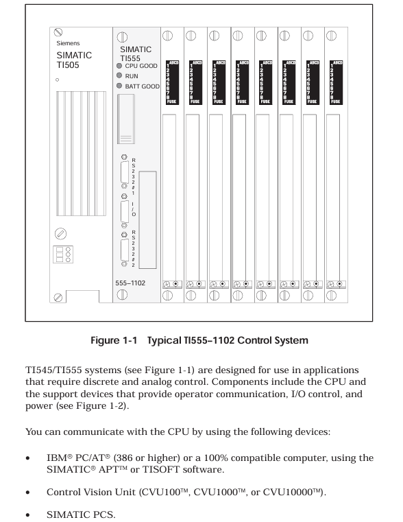
The SIMATIC TI545/TI555 controller system manual focuses on the hardware installation, system wiring, program storage, startup, and troubleshooting of TI545-1102 and TI555-1101/1102 CPUs. It specifies that the system supports Series 505 local base (4/8/16 slots) and Series 500 remote base (requires PPX: 500-5114A RBC conversion), and hardware installation must follow the power budget (+5V 55W, -5V 3.75W), grounding specifications (grounding resistance ≤ 0.1 Ω), and anti-interference design (shielded twisted pair, noise suppression); The program can be stored in EEPROM/EPROM (128K/256K bytes), and startup requires completing memory configuration (TI545 maximum 192K bytes, TI555-1102 maximum 1920K bytes) and I/O registration; Troubleshooting relies on LED status indication, auxiliary functions (AUX 10/11/12/20/25/29), and RS-485 cable detection (line resistance 52-87 Ω), while providing Series 500 system upgrade solutions to adapt to discrete/analog control scenarios in industrial automation.
Core characteristics of the system
Control capability: Supports discrete/analog control, can execute relay ladder logic (RLL), PID loop, special function program (SFPGM), supports 256 SF modules;
Communication ability:
Local communication: 2 RS-232/422/485 ports (baud rate 300-19200), supporting programming devices/printers/modems;
Remote I/O: 1 RS-485 I/O port, maximum connection to 15 remote bases, distance 3300 feet (1km);
Storage capacity: Supports EEPROM/EPROM non-volatile storage (128K/256K bytes), RAM configurable (TI545 up to 192K bytes, TI555-1102 up to 1920K bytes);
Compatibility: Supports Series 505 local dock and Series 500 remote dock (requires RBC conversion), compatible with old system upgrades.
Hardware Installation Specification
1. Base and module installation
(1) Base type and installation
Key requirements for base model, slot number, installation method
PPX: 505-6504 4 panel installation requires NEMA enclosure with a spacing of ≥ 6 inches (heat dissipation)
PPX: 505-6508 8-panel installation screw hole size as shown in Figure 3-4, torque 2.6-5.22 in lb
PPX: 505-6516 16 16 rack/panel installation compatible with 19 inch rack, depth 7.99 inches
Series 500 6/8/12/14/16 panel installation requires PPX: 500-514A RBC conversion to remote base
(2) CPU installation
Installation location: Series 505 base second slot (adjacent to the power supply);
Battery configuration: 3V rechargeable lithium battery, switch 9 (DIP switch) control enable, backup for 6 months at 0-60 ℃, BATT GOOD light flashes when low battery level;
DIP switch settings:
Switch 1: Port2 mode (left=RS-422, right=RS-485);
Switch 2: Port1 function (left=programming port, right=printer port);
Switch 3-5: Port 1 baud rate (On=1, Off=019200=On/On/On);
Switch 6-8: Port 2 baud rate (same as Port 1);
Switch 9: Battery Enable (Left=On, Right=Off).
(3) Installation of Remote Base Controller (RBC)
Applicable scenarios: Series 505 remote base with PPX: 505-6851A, Series 500 remote base with PPX: 500-5114A;
Installation location: Remote base second slot;
Key settings:
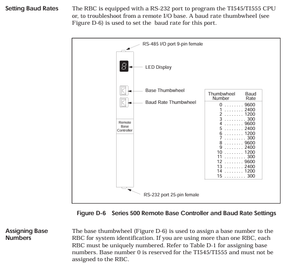
Base number: Thumbwheel set 1-15 (0 is the local base, not available);
Baud rate: PPX: 505-6851A uses DIP switch 2 (Table 3-4), PPX: 500-5114A uses Thumbwheel (Table D-1);
Output hold: When the jumper selects communication interruption, output "hold" or "turn off".
2. Power installation and budget
(1) Power supply model and parameters
Power supply model Input voltage Output power Applicable scenarios
PPX: 505-6660A 110/220V AC (jumper selection)+5V 55W, -5V 3.75W AC power supply scenario
PPX: 505-6663 20-30VDC+5V 55W, -5V 3.75W DC power supply scenario
(2) Power budget calculation
Total power=sum of all modules+5V power+sum of all modules -5V power, must be ≤ 55W (+5V) and 3.75W (-5V);
Typical module power: CPU 4W, RBC 5W, analog module 4-5W, see Appendix B Table B-1 for details.
3. Anti interference and grounding design
Noise suppression:
Noise source: motor, frequency converter, welding machine, with a spacing of ≥ 3 feet;
Suppression measures: Add RC/MOV buffer to inductive load (Figure 2-5/2-6), and use shielded twisted pair cable (12 twisted per foot) for signal;
Grounding specifications:
Grounding resistance ≤ 0.1 Ω, use # 8 copper wire to ground the electrode;
Controller grounding: base → cabinet → grounding electrode, remove the paint surface to ensure conductivity (Figure 2-9/2-10);
Shielded grounding: The input cable is shielded and grounded at the signal source end, and the output cable is shielded and grounded at the base end (single ended grounding).
System cabling and connections
1. Cable selection and wiring
(1) Key cable types
Recommended cable usage, key parameters, maximum length
RS-485 backbone Belden 9860 16AWG, impedance 124 Ω, capacitance 35.8pf/m 3300 feet (1006m)
RS-485 branch line Belden 9271 25AWG, impedance 124 Ω, capacitance 40pf/m 33 feet (10m)
RS-485 backup wire Belden 9182 22AWG, impedance 150 Ω, capacitance 28.9pf/m 2200 feet (670m)
Power connection wire 14AWG copper wire, temperature resistance ≥ 75 ℃, rated voltage ≥ 300V, short distance (≤ 10 meters)
(2) RS-485 wiring specification
Topology structure:
Main line: star (T-shaped) or bus type, avoiding multiple branches (Figure 4-8/4-9);
Terminal resistance: Add 120 Ω (9860/9271) or 150 Ω (9182) to both ends of the base, and do not add to the middle base;
Length limit:
2-5 terminal blocks: 9860 up to 3300 feet, 9182 up to 2200 feet;
16 terminal blocks: 9860 maximum 2200 feet, 9182 maximum 1467 feet (Table 4-2);
Wiring method: Underfloor/ceiling/surface trunking, avoid parallel connection with power cables (Figure 4-4/4-5).
2. Peripheral connection
Programming equipment: connected via Port1 (RS-232), distance ≤ 50 feet, using a 9-pin D-type connector (Figure 3-12);
Printer: Set Port1 as the printer port (switch 2 on the right), supporting XON/XOFF or READY/BUSY handshakes (Figure 4-13/4-14);
Modems: Port 1 connection, supports dedicated line (DCE interface, V.32 error correction) or dial-up (TIDIAL software required), unlimited distance (Figure 4-12).
Program Storage and System Startup
1. Program storage medium
Storage type, capacity, order number, key characteristics
EEPROM 128K bytes 2587681-8022 electrically erasable, supports RAM<->EEPROM replication, portable (Release 3.0+CPU universal)
EEPROM 256K bytes 2587681-8030 on the same left, with larger storage capacity
EPROM 128K byte 2587681-8023 UV erase, EEPROM copy required, not directly programmable
EPROM 256K bytes 2587681-8031 on the same left, with larger storage capacity
(2) EEPROM operation (AUX 84)
Copy RAM → EEPROM: The EEPROM needs to be erased first to ensure that the user program is ≤ 126K/254K bytes;
Copy EEPROM → RAM: If there is a program in EEPROM and the battery is damaged during power on, it will be automatically loaded into RAM;
Erase EEPROM: Select "Erase" for AUX 84, the program cannot be restored after erasing.
2. System startup process
(1) Initial startup steps
Initialize CPU:
Turn off the battery (switch 9 on the right), disconnect the power, and ensure that there is no EEPROM/EPROM;
Power on, CPU clears memory and enters Program mode;
Turn on the battery (left of switch 9), the BATT GOOD light will turn on (fully charged after 36 hours);
Configuration and Download:
Connect programming device (TISOFT 5.0+), configure memory (Table 6-1/6-2) and I/O base;
Download user program, JOG test actuator (motor/solenoid valve);
Switch to Run: Set the CPU to RUN mode and check that the CPU GOOD and RUN lights are on.
(2) Memory configuration (example)
CPU model, memory type, minimum capacity, maximum capacity, block size
TI545-1102 L (trapezoidal) 1K bytes 59K bytes 1K bytes (occupying 3K of system memory)
TI545-1102 V (variable) 1K bytes 177K bytes 1K bytes
TI555-1102 L (trapezoidal) 1K bytes 635K bytes 1K bytes (occupying 3K of system memory)
TI555-1102 V (variable) 1K bytes 1905K bytes 1K bytes

Troubleshooting and System Upgrade
1. Fault diagnosis tool
(1) LED status indication
LED name status meaning
CPU GOOD lights up. CPU has no fatal errors and is running normally
CPU GOOD extinguishes fatal errors (ROM failure, watchdog timeout, etc.)
RUN is on, CPU is in RUN mode
RUN flashing analog operation, discrete programming mode
BATT GOOD lights up, the battery is normal and enabled
BATT GOOD flashing battery charging or low battery level
BATT GOOD battery disabled or damaged
(2) Auxiliary functions (AUX)
Auxiliary Function Usage Key Operations
When the AUX 10 is powered on and the battery is restarted, it maintains V memory and clears memory when it is turned off
AUX 11 partially restarts to clear discrete I/O and maintain L/V/K/S memory
AUX 12 fully restarts and clears all I/O and timers/counters, downloads preset values
AUX 20 runs diagnostic tests on RAM/ROM/hardware, displaying the location of the fault
AUX 25 displays faulty I/O and lists unconfigured or faulty I/O modules
AUX 29 displays the diagnostic unit's scan time, mode, and battery status (Figure 7-1)
2. Common fault handling
Possible causes and solutions for the fault phenomenon
CPU GOOD ROM diagnostic failure, return to factory for repair
CPU GOOD extinguishes watchdog timeout check program scanning time, AUX 11 restarts
Communication failure RS-485 cable fault. Measure the inter line resistance (52-87 Ω) and check the terminal resistance
The battery light is flashing. If the battery is low after charging for 24 hours and still flashes, replace it
I/O unresponsive base unregistered AUX 25 check, reconfigure I/O
3. Series 500 system upgrade
(1) TI520/530 series upgrade
Hardware modification:
Remove the original controller/distributed base controller (DBC);
16/8 slot base with PPX: 500-5840 adapter, equipped with 24V power supply (PPX: 500-2151A);
Install PPX: 500-5114A RBC, with base numbers 1-15;
Wiring renovation:
RS-485 cable (Belden 9860) with a maximum backbone length of 3300 feet;
Add a 120 Ω resistor to the terminal block (base at both ends);
Software configuration:
Reconfigure I/O (base numbers 1-15) and download the program.
(2) TI560/565 series upgrade
RS-485 type: Remove the original CPU directly, connect the RS-485 cable to TI545/TI555 I/O ports, and change the base number to 1-15;
RF type: Add PPX: 505-6860 RF → RS-485 converter, then connect to TI545/TI555, change base number 1-15.
Appendix Key Information
1. Environmental Parameters (Appendix A)
Parameter indicators
Working temperature 0-60 ℃ (32-140 ℉)
Storage temperature -40-70 ℃ (-40-158 ℉)
Relative humidity 5% -95% (non condensing)
Vibration sine: 10-57Hz 0.15mm peak to peak value; Random: 57-150Hz 1.0g
Electrostatic discharge IEC 801-2 Level 4 (15kV)
Isolation Voltage Field - Controller 1500Vrms
2. Recommended spare parts (Appendix 7.9)
Base: PPX: 505-6504/6508/6516;
Power supply: PPX: 505-6660A/6663;
Fuse: 3A slow melting (6660A), 8A fast melting (6663);
Storage media: EEPROM 128K/256K, EPROM 128K/256K;
Cable: RS-232 programming cable (2601094-8001).
- OMRON
- ABB
- General Electric
- EMERSON
- Honeywell
- HIMA
- ALSTOM
- Rolls-Royce
- MOTOROLA
- Rockwell
- Siemens
- Woodward
- YOKOGAWA
- FOXBORO
- KOLLMORGEN
- MOOG
- KB
- YAMAHA
- BENDER
- TEKTRONIX
- Westinghouse
- AMAT
- AB
- XYCOM
- Yaskawa
- B&R
- Schneider
- KONGSBERG
- NI
- WATLOW
- ProSoft
- SEW
- ADVANCED
- Reliance
- TRICONEX
- METSO
- MAN
- Advantest
- STUDER
- DANAHER MOTION
- Bently
- Galil
- EATON
- MOLEX
- DEIF
- B&W
- ZYGO
- Aerotech
- DANFOSS
- Beijer
- Moxa
- Rexroth
- Johnson
- WAGO
- TOSHIBA
- BMCM
- SMC
- HITACHI
- HIRSCHMANN
- Application field
- XP POWER
- CTI
- TRICON
- STOBER
- Thinklogical
- Horner Automation
- Meggitt
- Fanuc
- Baldor
- SHINKAWA
- Other Brands
- UniOP
- KUKA
- Iba
- Beckhoff
- ADLINK
-
 Rolls Royce H1111.0204 Ship Main Controller
 -
 Basler Electric BE3-32-3AC Reverse Power Relay 9 1376 00 105
 -
 Basler Electric BE3-25-1A1N4 Synch Check Relay 9319100100
 -
 Basler Electric SR4A-2B15B3A Static Voltage Regulator
 -
 Basler Electric SR4A-2B15B3E Static Voltage Regulator
 -
 Basler Electric 9170818100 Solid State Protective Relay
 -
 Basler Electric AEC63-7 Analog Excitation Controller
 -
 Basler Electric 17483 Auxiliary Module
 -
 Basler Electric BE1-59 Over Voltage Relay
 -
 Basler Electric 21600-101 Control Module
 -
 Basler Electric KR2F Generator Voltage Regulator 9056600100
 -
 Basler BE1-CDS Current Differential System
 -
 Basler Electric CBS 212 Current Boost System 9 2650 00 100
 -
 Basler Electric IFM-150 Firing Circuit Chassis
 -
 Basler Electric BE1-60 Voltage Balance Relay C1F A1P D0C3F
 -
 Basler Electric BE1-32R Power Relay A2E D1R A0N0F
 -
Basler Electric BE1-32R Power Relay A2E D1R A0N0F
-
 Basler Electric 8650C80G01 Isolation Transducer PCB Board
 -
 ETEL EA-P2M-300-4/7.5A-0100-01 AccurET Modular 300 Servo Drive
 -
 Basler Electric 87T Transformer Differential Relay
 -
 Basler Electric BE-6868 Power Transformer 5950007559202
 -
 Basler Electric PRS250 Veri-Sync Relay 9088800102
 -
 Basler Electric SCP-250-G-60 VAR Power Factor Controller
 -
 Basler DECS-150 AVR 1NS2V1N1S Voltage Regulator
 -
 Basler UFOV 260A Under Frequency Overvoltage Module
 -
 Basler MOC2 199 Motor Operated Control – Overview and Setup
 -
 Basler BE3-49R-5K5A1 Temperature Relay – Complete Guide
 -
Basler BE 20035 001 Transformer – Technical Data and Installation
-
 Basler BE 02727 001 Transformer – Specifications and Usage
 -
 Basler BE127 Under Voltage Relay – Features and Application Guide
 -
Basler CBS377 Current Boost System – Complete Technical Guide
-
 Basler BE1-87G P/N 9170818100 Differential Relay – In-Depth Specs
 -
Basler BE1-87G Generator Differential Relay – Technical Overview
-
Basler Electric SR4A2B16 SVR Static Voltage Regulator – Complete Guide
-
 Basler Electric 9261500101 Power Supply Module
 -
 Basler Electric AEM-2020 Analog Expansion Module
 -
Basler Electric DGC-2020 Digital Genset Controller 51BRBNEAH001
-
Basler Electric BE1-59N Ground Fault Overvoltage Relay
-
 Basler Electric BE1-59N-A5E-E1L-N0S1F Neutral Overvoltage Relay
 -
Basler Electric MOC2499 Motor Operator Control Potentiometer 9072300430
-
 Basler Electric BE1-50/51M Overcurrent Relay
 -
 Basler Electric 9148100106 MOC3502 Solid State Relay 250VDC 0.25A
 -
 Basler Electric CBS 212 Current Boost System 9265000100
 -
 Basler Electric 10493002 Control Module
 -
Basler BE1-32R D3E E1R A0N1F Power Relay
-
 Basler SR8A2B15B3A Static Voltage Regulator
 -
 Basler IFM-105 Firing Circuit Chassis 9324100105
 -
Basler SR4A2B05B3A Static Voltage Regulator
-
 Basler BE151G1EB6PB0N0F Protective Relay
 -
Basler BE1-59 Electric Over Voltage Relay
-
 Basler 277 Static Programmable Powerline Carrier Channel
 -
 Basler BE1-32R D1E A1P A0N1F Power Relay
 -
Basler SR4A1B07B3A Static Voltage Regulator
-
 Basler Electric BE1-700 Digital Protective Relay
 -
Basler Electric SR8A-2B01B3A Static Voltage Regulator
-
 Basler Electric SR4A-2B01B3E Static Voltage Regulator
 -
 Basler Electric 9017709102 PC Board
 -
Basler Electric SR4A-2B01B3A Static Voltage Regulator
-
 Basler Electric PRS-250 Veri-Sync Relay
 -
 Basler Electric 9066800102 Excitation Support System
 -
Basler Electric BE1-87G Generator Differential Relay 9 1708 18 100
-
 Basler Electric 36T865-2 BE03752001 Power Supply
 -
 Basler Electric M-300 149D940G02 Power Supply
 -
 Basler Electric ACA2040-25GM 4Mp 25Fps Area Scan Camera
 -
 Basler BE1-87G-S1A-A1C-A0N0 Differential Relay
 -
Basler SR8A-2B06B3E Static Regulator SR8A2B06B3E
-
 Basler SCP-210 Frequency Controller 9095400100
 -
 Basler BE1-59-A3E-A1J-N1N3F Overvoltage Relay BE159A3EA1JN1N3F
 -
Basler 9 2011 11 100 Bracket Mounted Terminal Unit
-
Basler 9 1606 00 101 Voltage Regulator
-
 Basler CBS-377 Current Boost System 9109600102
 -
 Basler 8650C72 Exciter Control Module PCB Rev 5
 -
 Basler C2EE1PA0N1F BE1-32R Reverse Power Relay
 -
 ADLINK HPCI-14S12U - Industrial Control Backplane 12PCI Backplane PCI-14S Passive Backplane
 -
-0010.png) ADLINK PCIe-GIE74C - image acquisition card 4-CH GigE Vision PoE+ Frame Grabber
ADLINK PCIe-GIE74C - image acquisition card 4-CH GigE Vision PoE+ Frame Grabber -
-0010_1.png) ADLINK PCI-8164 - control card 4-Axis Advanced Motion Controller Board
ADLINK PCI-8164 - control card 4-Axis Advanced Motion Controller Board -
 ADLINK PCIe-U304 - 4 Port USB3 PCIe Frame Grabbers USB Screw Hole Card
 -
 ADLINK PCI-9112 - Multi-Function Data Acquisition Card DAQ Card
 -
 ADLINK PCI-7432 - 51-12013-0A50 4-CH Isolated Numérique I/O PCI Cartes Digital I/O Card
 -
 ADLINK PCA-6106P3-0C1 REV.C1 - backplane 6-Slot Passive Backplane Board
 -
 ADLINK PCI-7224 - 24-CH Opto-Isolated Digital I/O PCI Board
 -
 ADLINK CPCI-7433R(G) - Digital Input Board Rear I/O CompactPCI Card
 -
 ADLINK EBP-13E4 - 51-46703-0A30 Industrial PC Backplane Passive Backplane
 -
 ADLINK PCIE-HDV62 - Image acquisition card High Definition Video Frame Grabber
 -
 ADLINK EBP-13E4 - 51-46703-0A30 Industrial Backplane Board Passive Backplane
 -
 ADLINK 90111-B1 / CPCI-6770 - PCB CPU MODULE CompactPCI Single Board Computer
 -
 ADLINK PCI-7248 - DATA ACQUISITION PCI CARD 48-CH Parallel Digital I/O Board
 -
 ADLINK PCI-7230 - 51-12003-0a50 board PCI7230 32-CH Isolated Digital I/O Card
 -
 ADLINK PCI2A000CB - 51-20000-0B30 Multi-Function DAQ Card Baseboard
 -
 ADLINK PCI-8134-005 - 4-Axis Motion Controller Card
 -
 ADLINK PCI-7224 - 24-CH Opto-Isolated Digital I/O PCI Card
 -
 ADLINK PCI-7434 - 64-CH Isolated Digital Output Card
 -
 ADLINK PCI-8132 - motion control card 2-Axis Servo & Stepper Controller
 -
 ADLINK PCI-8134 - Motion Controller PCI Card 4-Axis Controller Board
 -
 ADLINK PCI-8164 - Motion Control Card 51-12406-0A40 4-Axis Controller
 -
 ADLINK 51-12001-0C20 - Circuit Board Data Acquisition Interface Module Hardware
 -
 ADLINK NuPR0-840 - industrial control motherboard Full-Size PICMG CPU Board
 -
 ADLINK PCI-7444 - 51-12023-0A10 card 128-CH Isolated Digital Output Board
 -
 ADLINK PCI-1612B - data acquisition card 4-Port RS-232/422/485 Serial Communication Card
 -
 ADLINK PCI-6208V 009 - 8/16-CH 16-Bit Analog Output Cards PCB-I-E-482=6BX3
 -
 ADLINK NUPRO-935A/LV - industrial control motherboard Full-Size PICMG SBC Board
 -
 ADLINK PCI-9114DG - Multi-Function DAQ Card Data Acquisition PCI Card
 -
 ADLINK ACL-7130 - Data acquisition card Isolated Digital I/O Board
 -
 ADLINK ABX-6300D-4E1-BP - board ABX6300D4E1BP Video Interface Expansion Card
 -
 ADLINK CPCI-6940 - CPCI-6940/D1539/M16-0(EA)-000E 6U CompactPCI Processor Board
 -
 ADLINK NuPRO-760 - industrial control motherboard Half-Size PICMG SBC CPU Board
 -
 ADLINK IMB-M42H (G)-0020 - industrial control motherboard LGA1155 Micro-ATX Mainboard
 -
 ADLINK RTV-24 / PCI-MP4S - 51-12519-1C30 4-Channel Real Time Video Capture Board
 -
 ADLINK PCI-8134 - 4-Axis Servo & Stepper Motion Controller Card
 -
 ADLINK MXC-6101D - V.PC000.002.ST.00 Box PC Configurable Embedded Computer
 -
.png) ADLINK PCI-8134A - 51-12421-0A10 Motion Control Card 4-Axis Controller Card
ADLINK PCI-8134A - 51-12421-0A10 Motion Control Card 4-Axis Controller Card -
 ADLINK DIN-100S / DIN-100SA1 - Technology SCSI-II TB 100-PIN Terminal Block Board
 -
.png) ADLINK DIN-812M001 / DIN812M001 - 51-14034-0A1 51140340A1 Terminal Module Breakout Interface
ADLINK DIN-812M001 / DIN812M001 - 51-14034-0A1 51140340A1 Terminal Module Breakout Interface -
_1.png) ADLINK PCI-8164 - Servo motion control 4-Axis Advanced Controller Card
ADLINK PCI-8164 - Servo motion control 4-Axis Advanced Controller Card -
 ADLINK PCIe-GIE64 - Acquisition card GigE Vision PoE+ Frame Grabber
 -
 ADLINK M-302 - Industrial control motherboard ATX PC Board Mainboard
 -
 ADLINK PCI-8134 - Motion Controller PCI Card 4-Axis Controller Board
 -
 ADLINK PCI-RTV24 - Image capture card Analog Video Frame Grabber
 -
 ADLINK PCI-8102 - Motion control card 2-Axis Servo & Stepper Controller Board
 -
 ADLINK PCI-9112 REV.B1 - Card Multi-Function Data Acquisition Card
 -
 ADLINK HSI-DI32-M-N / HSL-TB32-M-DIN - Discrete I/O MODULE Distributed Automation Module System
 -
 ADLINK PCI-7296 - IO card REV.A3 96-CH Parallel Digital I/O Card
 -
-0020.png) ADLINK DIN-814P-A4 / 814Y - terminal board Motion Control Interface Block
ADLINK DIN-814P-A4 / 814Y - terminal board Motion Control Interface Block -
 ADLINK DIN-814P-A4 - 51-14056-0A10 PCB-I-E-2736=ZA01 Screw Terminal Board Breakout
 -
 ADLINK M-322 - motherboard Industrial Control Computer Mainboard
 -
 ADLINK NUPRO-406 REV:B1 - industrial control motherboard Full-Size PICMG CPU Board
 -
 ADLINK AMP-204C - card DSP-Based 4-Axis Advanced Pulse-Train Controller
 -
 ADLINK HPCI14S REV.B1 - industrial computer baseboard 14-Slot Passive Backplane


