SIEMENS SIMATIC TI545/TI555 Controller
SIEMENS SIMATIC TI545/TI555 Controller
Overview
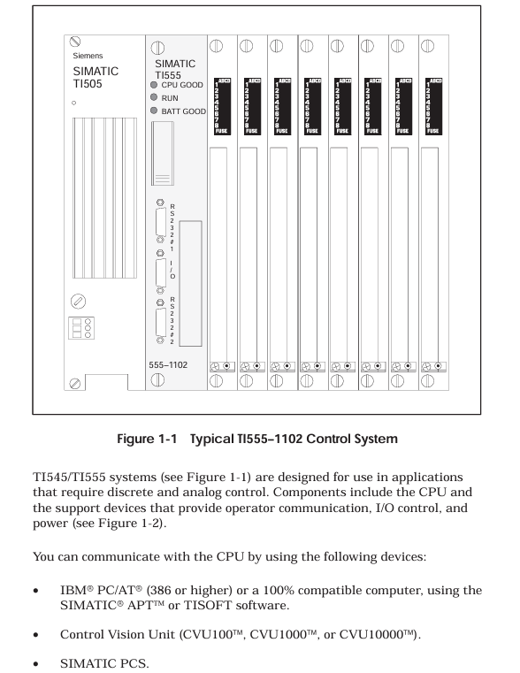
The SIMATIC TI545/TI555 controller system manual focuses on the hardware installation, system wiring, program storage, startup, and troubleshooting of TI545-1102 and TI555-1101/1102 CPUs. It specifies that the system supports Series 505 local base (4/8/16 slots) and Series 500 remote base (requires PPX: 500-5114A RBC conversion), and hardware installation must follow the power budget (+5V 55W, -5V 3.75W), grounding specifications (grounding resistance ≤ 0.1 Ω), and anti-interference design (shielded twisted pair, noise suppression); The program can be stored in EEPROM/EPROM (128K/256K bytes), and startup requires completing memory configuration (TI545 maximum 192K bytes, TI555-1102 maximum 1920K bytes) and I/O registration; Troubleshooting relies on LED status indication, auxiliary functions (AUX 10/11/12/20/25/29), and RS-485 cable detection (line resistance 52-87 Ω), while providing Series 500 system upgrade solutions to adapt to discrete/analog control scenarios in industrial automation.
Core characteristics of the system
Control capability: Supports discrete/analog control, can execute relay ladder logic (RLL), PID loop, special function program (SFPGM), supports 256 SF modules;
Communication ability:
Local communication: 2 RS-232/422/485 ports (baud rate 300-19200), supporting programming devices/printers/modems;
Remote I/O: 1 RS-485 I/O port, maximum connection to 15 remote bases, distance 3300 feet (1km);
Storage capacity: Supports EEPROM/EPROM non-volatile storage (128K/256K bytes), RAM configurable (TI545 up to 192K bytes, TI555-1102 up to 1920K bytes);
Compatibility: Supports Series 505 local dock and Series 500 remote dock (requires RBC conversion), compatible with old system upgrades.
Hardware Installation Specification
1. Base and module installation
(1) Base type and installation
Key requirements for base model, slot number, installation method
PPX: 505-6504 4 panel installation requires NEMA enclosure with a spacing of ≥ 6 inches (heat dissipation)
PPX: 505-6508 8-panel installation screw hole size as shown in Figure 3-4, torque 2.6-5.22 in lb
PPX: 505-6516 16 16 rack/panel installation compatible with 19 inch rack, depth 7.99 inches
Series 500 6/8/12/14/16 panel installation requires PPX: 500-514A RBC conversion to remote base
(2) CPU installation
Installation location: Series 505 base second slot (adjacent to the power supply);
Battery configuration: 3V rechargeable lithium battery, switch 9 (DIP switch) control enable, backup for 6 months at 0-60 ℃, BATT GOOD light flashes when low battery level;
DIP switch settings:
Switch 1: Port2 mode (left=RS-422, right=RS-485);
Switch 2: Port1 function (left=programming port, right=printer port);
Switch 3-5: Port 1 baud rate (On=1, Off=019200=On/On/On);
Switch 6-8: Port 2 baud rate (same as Port 1);
Switch 9: Battery Enable (Left=On, Right=Off).
(3) Installation of Remote Base Controller (RBC)
Applicable scenarios: Series 505 remote base with PPX: 505-6851A, Series 500 remote base with PPX: 500-5114A;
Installation location: Remote base second slot;
Key settings:
Base number: Thumbwheel set 1-15 (0 is the local base, not available);
Baud rate: PPX: 505-6851A uses DIP switch 2 (Table 3-4), PPX: 500-5114A uses Thumbwheel (Table D-1);
Output hold: When the jumper selects communication interruption, output "hold" or "turn off".
2. Power installation and budget
(1) Power supply model and parameters
Power supply model Input voltage Output power Applicable scenarios
PPX: 505-6660A 110/220V AC (jumper selection)+5V 55W, -5V 3.75W AC power supply scenario
PPX: 505-6663 20-30VDC+5V 55W, -5V 3.75W DC power supply scenario
(2) Power budget calculation
Total power=sum of all modules+5V power+sum of all modules -5V power, must be ≤ 55W (+5V) and 3.75W (-5V);
Typical module power: CPU 4W, RBC 5W, analog module 4-5W, see Appendix B Table B-1 for details.
3. Anti interference and grounding design
Noise suppression:
Noise source: motor, frequency converter, welding machine, with a spacing of ≥ 3 feet;
Suppression measures: Add RC/MOV buffer to inductive load (Figure 2-5/2-6), and use shielded twisted pair cable (12 twisted per foot) for signal;
Grounding specifications:
Grounding resistance ≤ 0.1 Ω, use # 8 copper wire to ground the electrode;
Controller grounding: base → cabinet → grounding electrode, remove the paint surface to ensure conductivity (Figure 2-9/2-10);
Shielded grounding: The input cable is shielded and grounded at the signal source end, and the output cable is shielded and grounded at the base end (single ended grounding).

System cabling and connections
1. Cable selection and wiring
(1) Key cable types
Recommended cable usage, key parameters, maximum length
RS-485 backbone Belden 9860 16AWG, impedance 124 Ω, capacitance 35.8pf/m 3300 feet (1006m)
RS-485 branch line Belden 9271 25AWG, impedance 124 Ω, capacitance 40pf/m 33 feet (10m)
RS-485 backup wire Belden 9182 22AWG, impedance 150 Ω, capacitance 28.9pf/m 2200 feet (670m)
Power connection wire 14AWG copper wire, temperature resistance ≥ 75 ℃, rated voltage ≥ 300V, short distance (≤ 10 meters)
(2) RS-485 wiring specification
- ABB
- General Electric
- EMERSON
- Honeywell
- HIMA
- ALSTOM
- Rolls-Royce
- MOTOROLA
- Rockwell
- Siemens
- Woodward
- YOKOGAWA
- FOXBORO
- KOLLMORGEN
- MOOG
- KB
- YAMAHA
- BENDER
- TEKTRONIX
- Westinghouse
- AMAT
- AB
- XYCOM
- Yaskawa
- B&R
- Schneider
- Kongsberg
- NI
- WATLOW
- ProSoft
- SEW
- ADVANCED
- Reliance
- TRICONEX
- METSO
- MAN
- Advantest
- STUDER
- KONGSBERG
- DANAHER MOTION
- Bently
- Galil
- EATON
- MOLEX
- Triconex
- DEIF
- B&W
- ZYGO
- Aerotech
- DANFOSS
- Beijer
- Moxa
- Rexroth
- Johnson
- WAGO
- TOSHIBA
- BMCM
- SMC
- HITACHI
- HIRSCHMANN
- Application field
- XP POWER
- CTI
- TRICON
- STOBER
- Thinklogical
- Horner Automation
- Meggitt
- Fanuc
- Baldor


