
GE VMIVME-1128 128 bit high-voltage digital input board
An open circuit can provide logic 0 or (jumper optional) logic 1.
Equipped with onboard built-in test (BIT) logic for fault detection and isolation, the front panel is equipped with a fault LED.
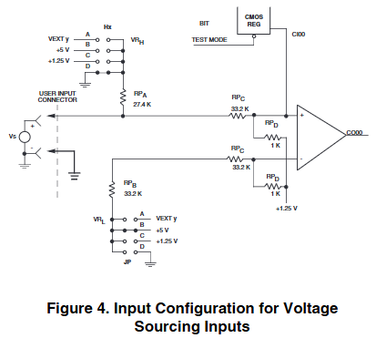
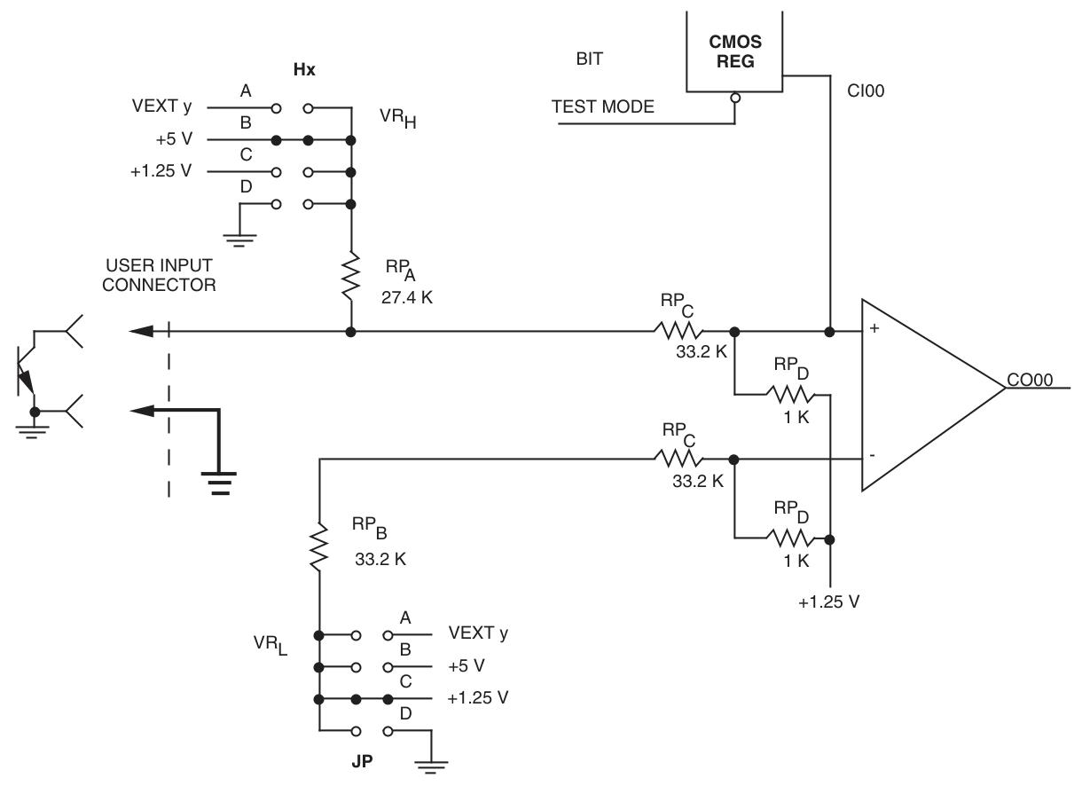
Users can choose the input voltage threshold (0.61 to 34V), with an input range of 0 to 66V (see Table 1).
Compliant with VMEbus specification Rev. C. 1, supports A24: A16: D32/D16/D08 (EO), from device address 39/3D: 29/2D.
Adopting a dual Eurocard shape (6U), equipped with high reliability DIN type I/O connectors, compatible with VMIC's intelligent I/O controllers (VMIVME-90xx series) and universal I/O controllers (VMIVME-9300 series).
GE VMIVME-1128 128 bit high-voltage digital input board
Basic characteristics
Equipped with 128 bit high-voltage digital inputs, with 8 inputs per group, the monitoring voltage source or current sinking signal can be selected through jumper wires.
An open circuit can provide logic 0 or (jumper optional) logic 1.
Equipped with onboard built-in test (BIT) logic for fault detection and isolation, the front panel is equipped with a fault LED.
Users can choose the input voltage threshold (0.61 to 34V), with an input range of 0 to 66V (see Table 1).
Compliant with VMEbus specification Rev. C. 1, supports A24: A16: D32/D16/D08 (EO), from device address 39/3D: 29/2D.
Adopting a dual Eurocard shape (6U), equipped with high reliability DIN type I/O connectors, compatible with VMIC's intelligent I/O controllers (VMIVME-90xx series) and universal I/O controllers (VMIVME-9300 series).
Application area
Automatic testing equipment, control system input, data acquisition system, digital input status monitoring, universal digital input, low maintenance application (BIT), status sensor monitoring, monitoring system, etc.
Functional feature details
Compliance and Appearance: Compliant with VMEbus specifications (ANSI/IEEE STD 1014-1987, IEC 821 and 297), with an appearance of 6U.
Input connector type: Use two 96 pin female connectors. For large-scale termination (IDC), it is recommended to use ERNI IDC DIN connectors and 0.033-inch 30 AWG ribbon cables; For discrete lines, Harting connectors and related accessories are recommended, and any connector requires a housing with a fixed lever. Harting housing is recommended.
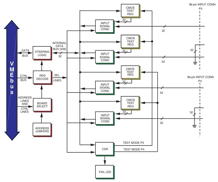
I/O organization: 16 input ports, each 8-bit wide, with a total of 128 inputs, addressable to any address within the short monitoring and/or short non privileged or standard monitoring data and/or standard non privileged data I/O mapping.
Addressing scheme: 32 bytes can be individually addressed on 8-bit, 16 bit, or 32-bit boundaries. There are board ID register, control and status register (CSR), and 16 input bytes on the board. 20 jumpers determine the base address of the board, and another jumper is used for standard or short I/O access, providing the relative position address mapping of each register.
Input circuit characteristics: The input is single ended, with a high input impedance (15k). The threshold accuracy is usually 10% in the input range of 3 to 66V, and ± 200mV in the input range of 0V to 3V. Please refer to the relevant charts and Table 1 for threshold levels.
Ordering information
ABC=000 in the ordering options (reserved for future use).
Provided descriptions and I/O connector models corresponding to different connector styles, as well as models of Harting crimping tools, and also provided contact information.
Built in testing (BIT)
The design has built-in testing logic, supports board level diagnostics, and can test all onboard active components. Provide special output registers for testing input circuits, controlled by the test mode bit in CSR. The fault LED on the front panel lights up when powered on, and can be turned off through program control after successfully completing user-defined diagnostic software.
Physical/Environmental Characteristics
Temperature range: storage -20 to 85 ° C, operation 0 to 55 ° C.
Relative humidity range: Non condensing 20 to 80%.
Altitude: Working up to 10000 feet.
Cooling method: forced air convection.
Size: Dual Eurocard (6U), 160 × 233.35mm.
Power requirement: Typical value of 2.31A at 5V, can be connected at the front panel (P3 or P4) or P2, VMIC provides recommended VMIAC-0129 P2 power accessories.
Mean Time Between Failures (MTBF): 228636 hours (30 ° C Bellcore method).
- OMRON
- ABB
- General Electric
- EMERSON
- Honeywell
- HIMA
- ALSTOM
- Rolls-Royce
- MOTOROLA
- Rockwell
- Siemens
- Woodward
- YOKOGAWA
- FOXBORO
- KOLLMORGEN
- MOOG
- KB
- YAMAHA
- BENDER
- TEKTRONIX
- Westinghouse
- AMAT
- AB
- XYCOM
- Yaskawa
- B&R
- Schneider
- KONGSBERG
- NI
- WATLOW
- ProSoft
- SEW
- ADVANCED
- Reliance
- TRICONEX
- METSO
- MAN
- Advantest
- STUDER
- DANAHER MOTION
- Bently
- Galil
- EATON
- MOLEX
- DEIF
- B&W
- ZYGO
- Aerotech
- DANFOSS
- Beijer
- Moxa
- Rexroth
- Johnson
- WAGO
- TOSHIBA
- BMCM
- SMC
- HITACHI
- HIRSCHMANN
- Application field
- XP POWER
- CTI
- TRICON
- STOBER
- Thinklogical
- Horner Automation
- Meggitt
- Fanuc
- Baldor
- SHINKAWA
- Other Brands
- UniOP
- KUKA
- Iba
- Beckhoff
- ADLINK
-
 ETEL DSCDP324-322F-000C Dual Motor Driver
 -
 ETEL EA-P2M-400-10/20A Position Controller
 -
 ETEL DSC2P121 and DSO-HIO33 Servo Amplifier Set
 -
 ETEL EA-P2M-400-15/40A AccurET Drive
 -
 ETEL EA-P2M-300-07/15A Position Controller
 -
 ETEL EA-P2M-048-05/10A-0100-01 Servo Drive
 -
 ETEL EA-S0M-300-40/80A Servo Drive Guide
 -
 ETEL DSB2P131-111E-000H Digital Servo Amplifier
 -
 ETEL DSCDP334-421-000 Servo Drive Guide
 -
ETEL EA-S0M-300-40 80A-0000-00 Motion Control Module
-
 ETEL UltimET Light Motion Controller EU-LGP-0-0-1000-01 Multi-Axis
 -
 ETEL DSO-RAC601-029 Controller Rack
 -
 ETEL DSMAX212-121C-000C Board
 -
 ETEL DSCDL132-212B-000C Position Controller
 -
 ETEL TMB0291-050-3TDS-E82 Torque Motor
 -
 ETEL DSMAX212-121-000 Board
 -
 ETEL DSB2P131-111E-000H Digital Servo Controller Amplifier Unit
 -
 ETEL DSB 2S 124-211E-000H Digital Servo Amplifier
 -
 ETEL AccurET EA-P2M-300-4/7.5A-0100-01 Modular Position Controller
 -
 Beckwith Electric M-6280A Digital Capacitor Bank Control
 -
 Beckwith M-2355B Adapter Panel with M-2001C-6SL Tapchanger Control
 -
 Beckwith M-0359 Syncrocloser MOD512
 -
Beckwith Electric M-2001C-6ELFA Tap Changer Controller
-
 Beckwith M-3311A 4-Coil Transformer Protection Relay
 -
 Beckwith M-0124 Terminal Board Adapter Plate Guide
 -
 Beckwith Pride M-0296C 3-Phase Programmable Relay
 -
 Beckwith M-0388 Syncrocloser Check Relay Guide
 -
 Beckwith M-0170A AC Current Relay Guide
 -
Beckwith M-3311 Transformer Protection Relay Guide
-
Beckwith Electric M3310 Integrated Transformer Protection Panel
-
 Beckwith M-0145 First Customer Protector
 -
Beckwith M-0170A AC Current Relay
-
 Beckwith PRIDE M-0296C 3 Phase Programmable Relay
 -
 Beckwith Pride M-0296b 3-Phase Programmable Relay
 -
Beckwith M-0245C High Speed Sync-Check Relay Guide
-
 Beckwith M-0115A AC Parallel Balancing Module
 -
Beckwith M-0389 Voltage Verifier Relay
-
Beckwith M-0115A Parallel Balancing Module
-
 Beckwith M-0389 Voltage Verifier
 -
 Beckwith PRIDE M-0420 Multifunction Relay Protection Module 48VDC
 -
 Beckwith Electric M-3430 Generator Protection Relay
 -
 Beckwith Electric M-0067E Tapchanger Control
 -
 Beckwith Electric M-0420 Multifunction Relay
 -
Beckwith Electric M-2001D-6L4S20C0S0X Tap Changer Control
-
 Beckwith Electric M3425A-STD1 Generator Protection Relay
 -
Beckwith Electric M-0245C High Speed Sync-Check Relay
-
Beckwith Electric M-3520 Intertie Protection Relay Guide
-
Beckwith Electric M-2001C-6SL Tap Changer Control
-
Beckwith Electric M-2001C Tap Changer Control Guide
-
Beckwith 35-12-635 Generator Protection Keypad Interface
-
Beckwith Electric P-2216 Generator Protection Main Board
-
 Beckwith Electric M-2293 Tap Changer Control Guide
 -
 Beckwith M-4272-6AB1EH0 Integrated Synchronizing Motor Bus Transfer
 -
Beckwith Electric M-4272 Motor Bus Transfer 60-140V 50/60Hz
-
Beckwith Electric M-2001B TapChanger Control
-
Beckwith Electric M-0193B Synchrocloser Unit
-
Beckwith Electric M-0115A AC Parallel Balancing Module
-
Beckwith Electric M-0169A Current Transformer
-
 Beckwith Electric P-1939 Generator Protection Annunciator Panel
 -
Beckwith Electric M-3311A Transformer Protection Relay Guide
-
Beckwith Electric M-0245B High Speed Sync-Check Relay
-
Beckwith Electric M3420 Generator Protection Relay
-
 Beckwith M-0193B Syncrocloser Unit
 -
 Beckwith Electric M-520 Intertie Protection Relay
 -
 Beckwith Electric M-3425A Generator Protection Relay
 -
Beckwith M-3425 Integrated Generator Protection Relay
-
Beckwith M-0115A Parallel Balancing Module
-
Beckwith Electric M-4272 Integrated Synchronizing Motor Bus Transfer
-
Beckwith Electric M-3420 Generator Protection System
-
Beckwith M-0193 Syncrocloser Unit
-
 Basler Electric DECS-250-CN1SN1N Digital Excitation Control System
 -
 Basler Electric BE1-700 E0N2X1N Digital Protective Relay
 -
 Basler Electric SR4A-2B15B3A Static Voltage Regulator 120VAC 50/60Hz
 -
 Basler Electric 9261402111 PCB Control Board 9346000033
 -
 Basler Electric BE28053-002 Transformer BE28053002
 -
 Basler Electric BE3-25A Auto Synchronizer B1D Sync Module
 -
 Basler Electric BE3-GPR Generator Protective Relay
 -
 Basler Electric SCP-250-G-60 VAR Power Factor Controller 9 1100 00 109
 -
 Basler Electric BE3-32-1S1N1 Reverse Power Relay 277V 5A
 -
 Basler Electric ACA1300-60GM Area Scan Camera 106200-17
 -
 Basler Electric UFOV 260 A Protection Module Specs
 -
 Basler Electric BE03303001 Control Module
 -
Basler Electric BE3-GPR-P1BVSF Generator Protective Relay
-
 Basler Electric BE1-87G Solid State Protective Relay Guide
 -
 BASLER ELECTRIC BE1-60 VOLTAGE BALANCE RELAY T176884
 -
 Basler Electric BE1-32R Protective Relay
 -
 Basler Electric 9022900-103 Transformer 6-7VA 60Hz
 -
 Basler Electric BE1-59-A4E-E1K-B1S3F Overvoltage Relay
 -
 Basler Electric KR2FF-M Voltage Regulator 9 1163 00 103
 -
 Basler Electric UFOV 260 A Protective Module
 -
 Basler Electric PCB Assembly 9059701100 919620
 -
 Basler Electric SR8A2B01A3E Static Voltage Regulator
 -
 Basler Electric SSR125-12 Static Voltage Regulator 9185900102
 -
 Basler Electric SSR 63-12 Static Voltage Regulator 600VAC
 -
 Basler Electric BE1-60 Solid State Protective Relay
 -
 Basler Electric BE3-47N/27-3A4N2 Voltage Relay 9320400101
 -
 Basler Electric BE1-59 Over Voltage Relay
 -
 Basler Electric DECS100-B15 Automatic Voltage Regulator
 -
 Basler Electric PRS250 Veri-Sync Relay 9088800102
 -
Basler Electric BE25927001 Current Transformer 1:34 Amp
-
Basler Electric 9170818100 Generator Differential Relay
-
 Basler Electric BE1-59N Solid State Ground Fault Overvoltage Relay
 -
 Basler Electric 1783 DC Current Transformer Coil 1200:5A
 -
Basler Electric BE1-67 Ground Directional Overcurrent Relay
-
 Basler Electric UFOV-260A Underfrequency Overvoltage Module
 -
 Basler Electric BE10493001 Control Module
 -
Basler Electric SSR125-12 Static Voltage Regulator Guide
-
 Basler Electric BE1810/U-2 Solid State Frequency Relay Guide
 -
 Basler Electric 9105100106 UFOV-250A Protector Guide
 -
 Basler Electric MOC2199 9072300-335 Relay Module Guide
 -
 Basler Electric 9289902106 Circuit Board
 -
Basler Electric BE1-32R Protective Relay A1E E1P BOS1P
-
 Basler Electric RAL6144-16GM GigE Line Scan Camera with Lens
 -
 Basler Electric BE3-49R-5I5A1 Temperature Relay
 -
 Basler Electric BE1-32R Power Relay B3E E1R A0N1F
 -
 Basler Electric SR4A2B06B3A Static Voltage Regulator Features
 -
 Basler Electric 9121000106 Manual Voltage Control MVC Guide
 -
Basler Electric SR32A-2B15B3E Static Voltage Regulator
-
 Basler Electric SR4A2B06B3A Static Voltage Regulator Guide
 -
Basler Electric 801A193F02 Hammond Transformer Module
-
 Basler Electric BE1-24 Volts Per Hertz Relay A1E F1J D1S0F
 -
 Basler Electric AEC63-7 Analog Excitation Controller 220-277V
 -
Basler Electric BE132R Power Relay T245579
-
 Basler Electric MVC 108 Manual Voltage Control 90 37000 102
 -
 Basler Electric 9022900-103 Control Transformer 6-7VA 60Hz
 -
 Basler Electric BE1-79M Plug Adapter 9170111102
 -
 Basler Electric 9 2007 00 100 Current Boost System CBS 305
 -
 Basler Electric SR4A2B01B3A Static Voltage Regulator 120V


